Automotive Gauge Cluster

Aug 2019 - Dec 2019
-
Design and build an embedded system that employs most of the concepts discussed in the EGR326 Embedded Systems Design course.
This is an exercise in translating a set of customer requirements into the design of an embedded system and working prototype to demonstrate desired and enhanced features.
The system to be designed and built this term is an automotive style dashboard. The heart of your system is your TI MSP432 Launchpad microcontroller board. It interfaces with a real time clock IC and several sensors that comprise the Dashboard system. Combined with some pushbutton switches, analog sensors, two stepper motors, a rotary encoder, and a display, you will design and build a prototype to evaluate usability and feasibility of desired features of the customer.
-
Mechanical:
Overall design
3D modeling
Electrical:
Wire routing, protection, and isolation
Wiring harnesses
Breadboard component layouts
Soldering
Software:
All software and functionality
Production:
Laser cutting and bending
Complete assembly
-
Lessons:
In order to meet timelines and prevent increases in cost due to implementing new features, its very important to mitigate scope creep. One way to do this is to reference the customers requirements frequently and focus on what's necessary rather than "nice-to-haves".
Outcome:
I focused more on implementing cool ideas rather than focusing on the requirements. The project was successful, but its late delivery and lack of some required functionality cost me points on its overall grade.
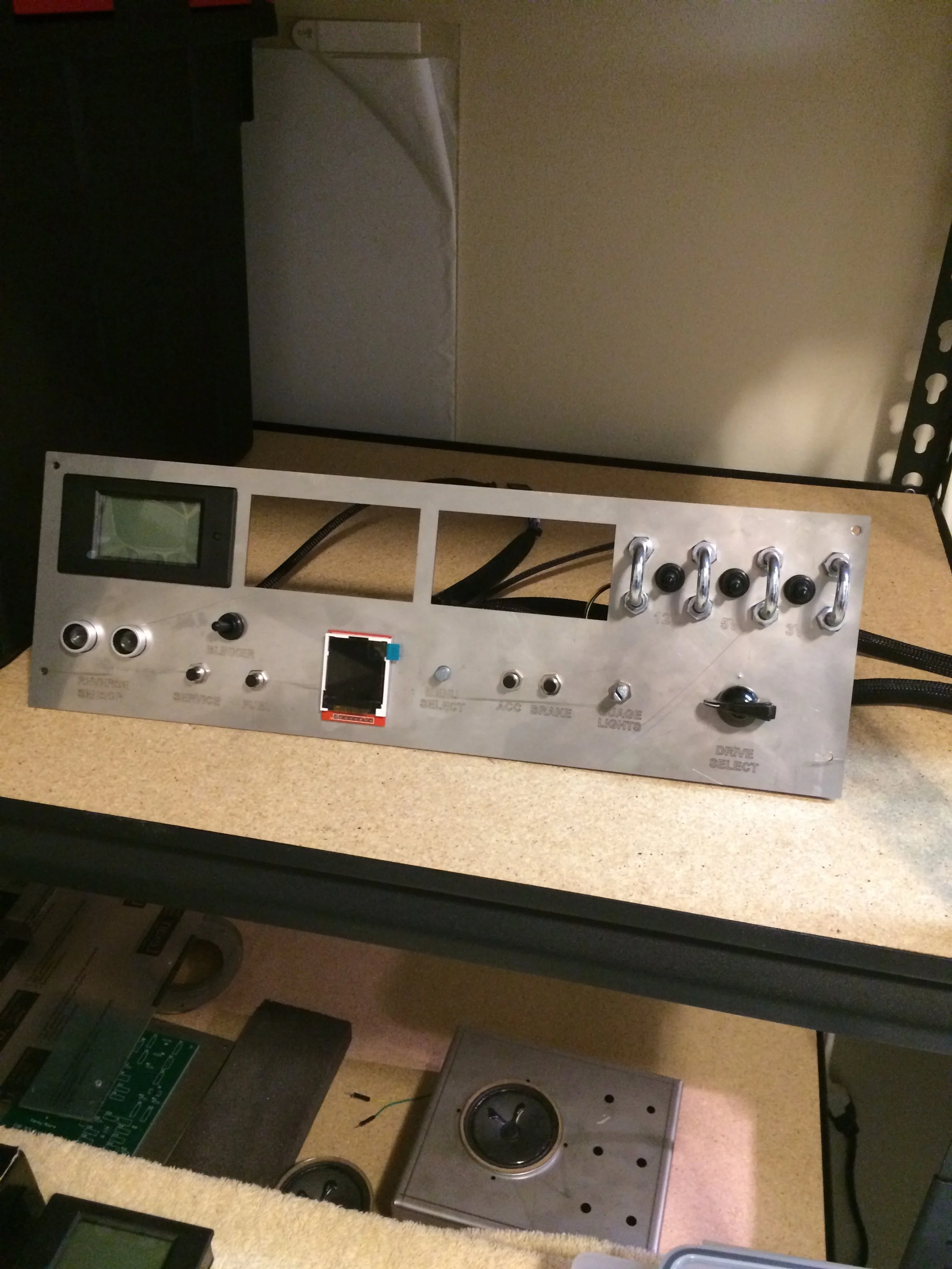
Overview
A free standing automotive gauge cluster. Users can interact with the components of the gauge cluster via the control panel on the front and have access to different features depending on what drive mode they have selected.
↓↓ Photos ↓↓
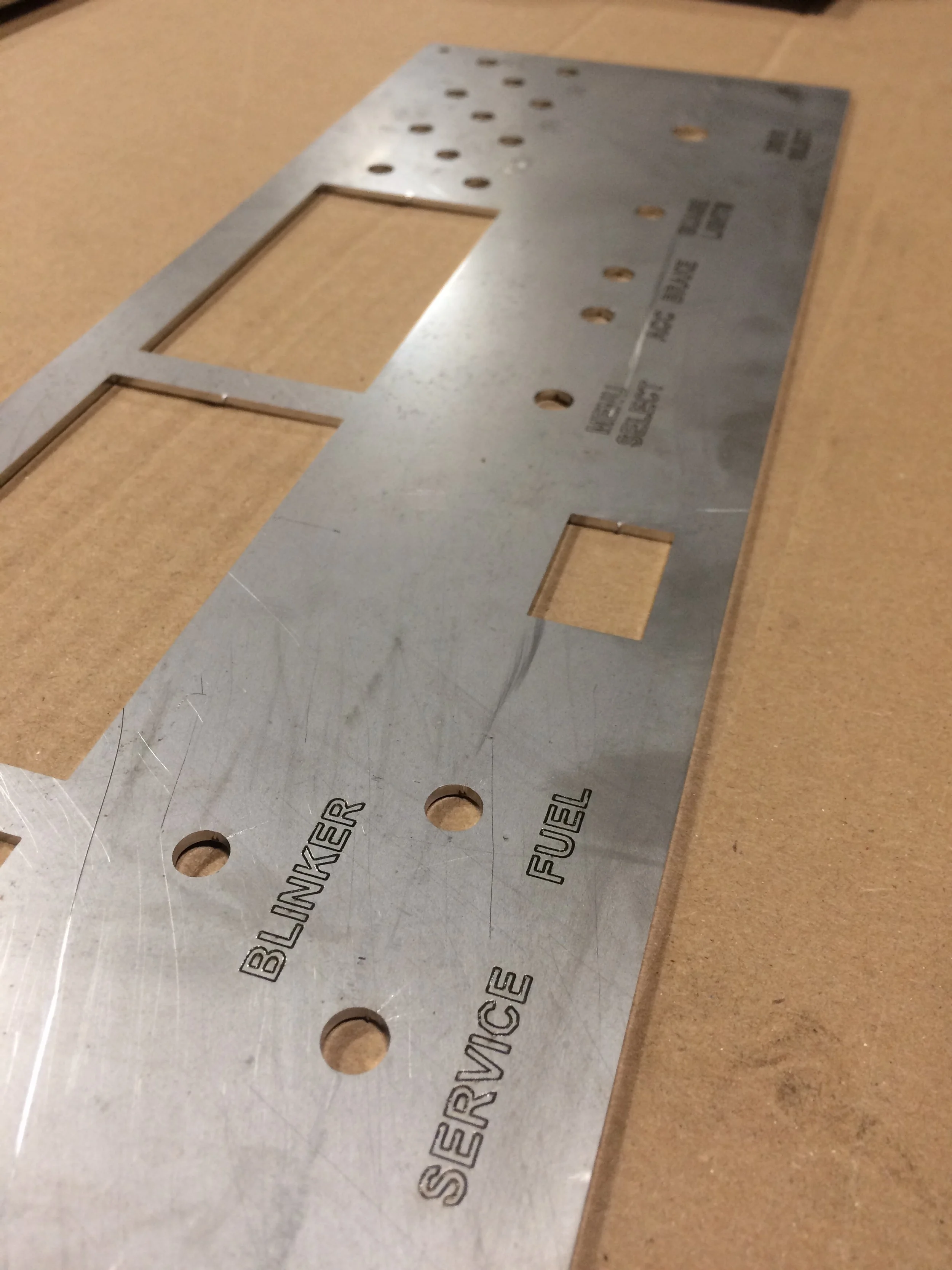
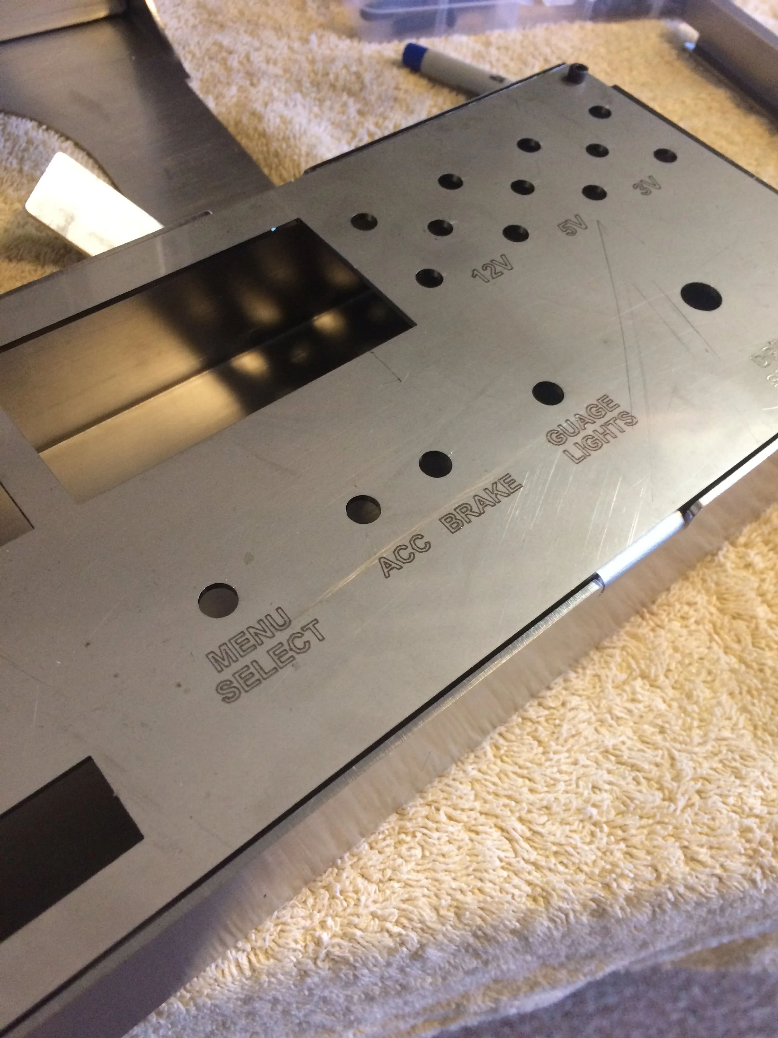
Concept Generation
These photos display some of the design progression during the initial phases of the project.
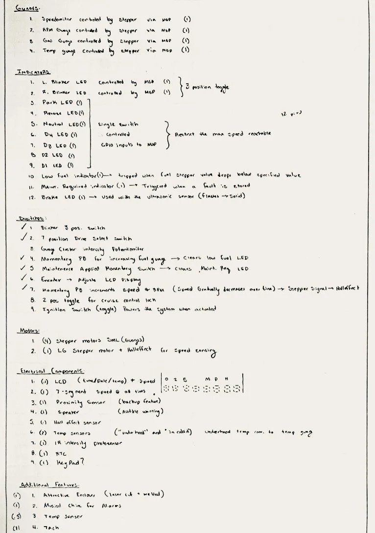
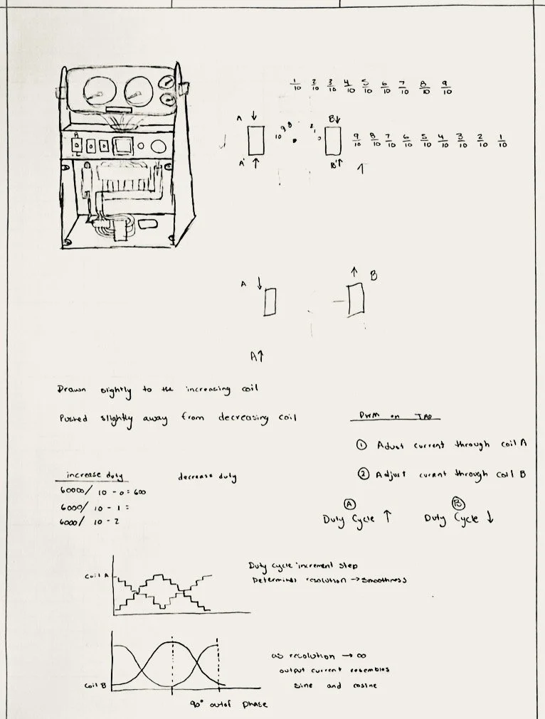
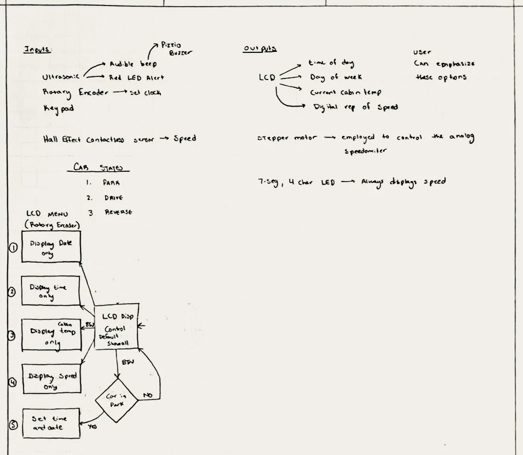
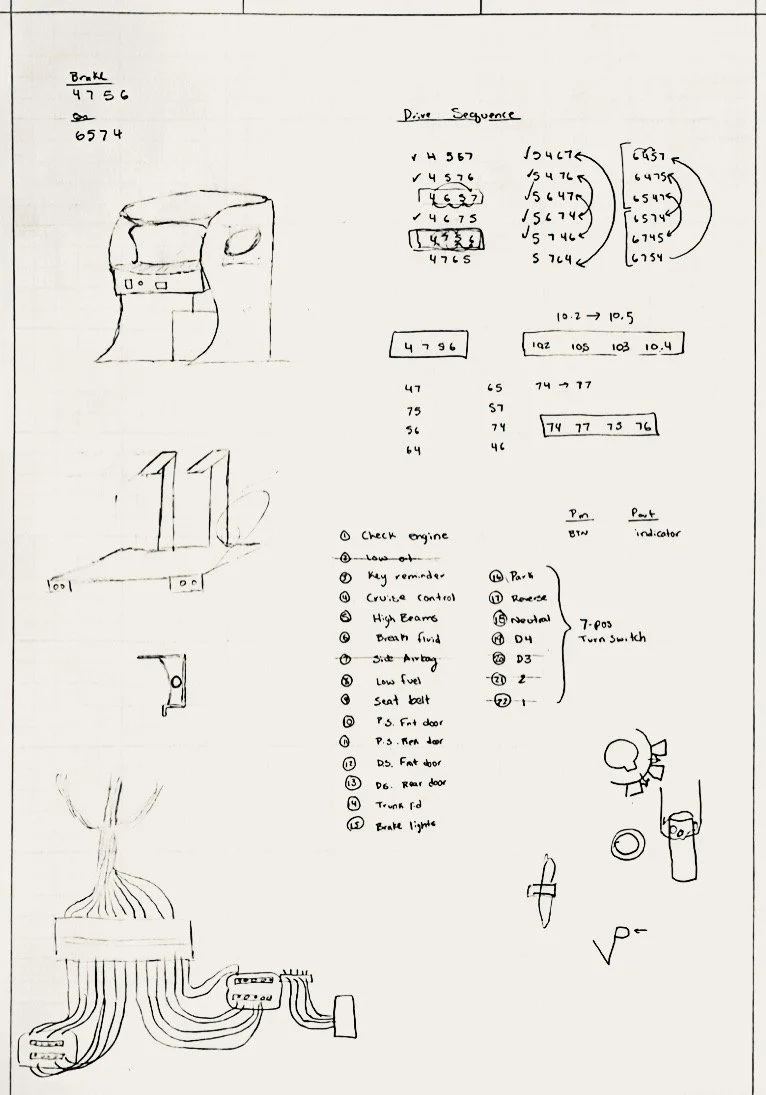
Software Design
Th software is controlled via a 6 position switch which acts as the “drive select” in a vehicle. Depending on its position, (off, park, drive, reverse) the software determines what features the user has access to.


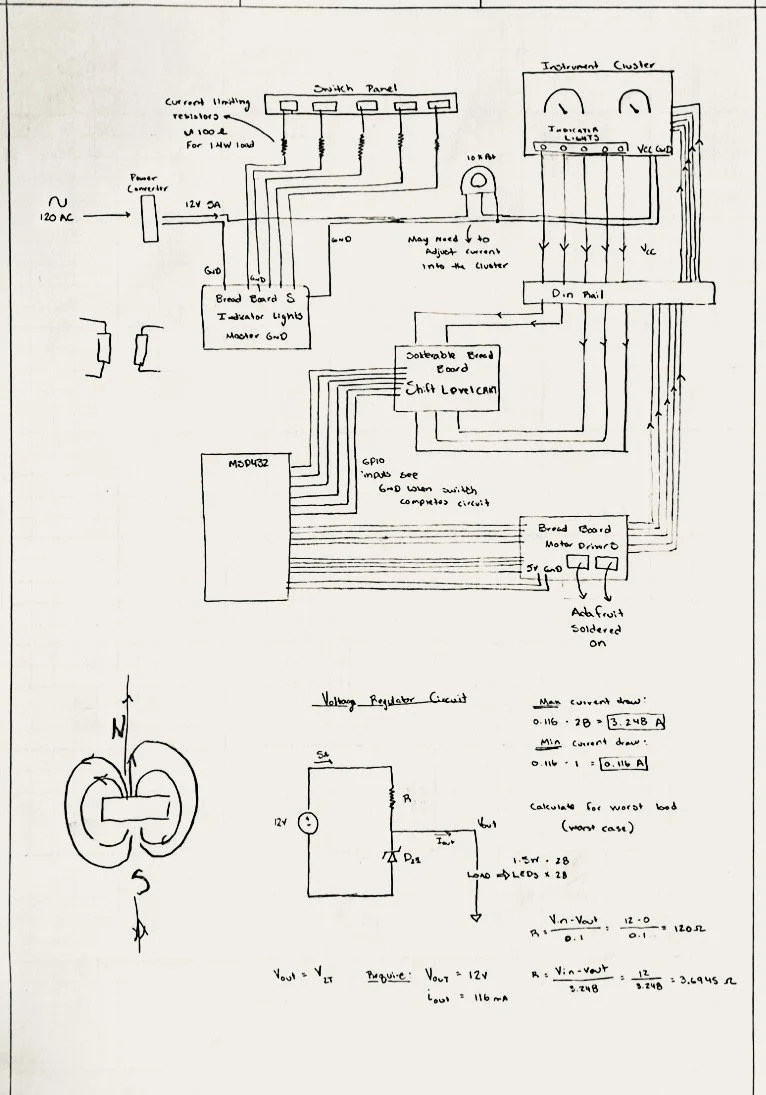
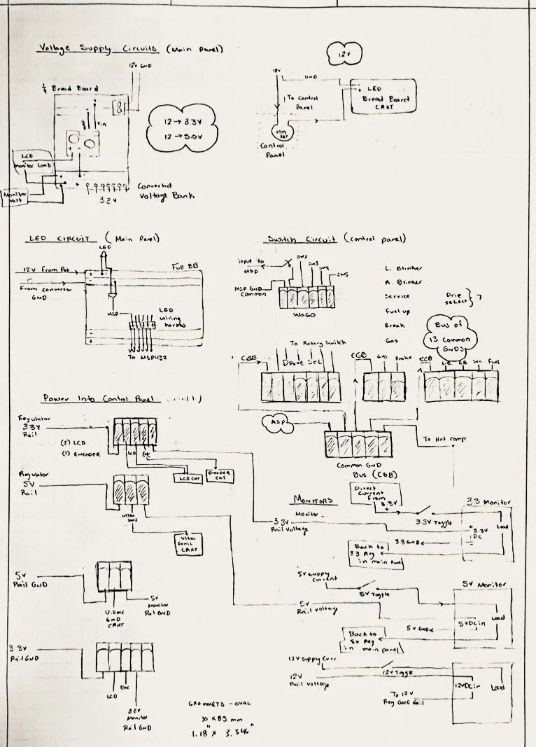
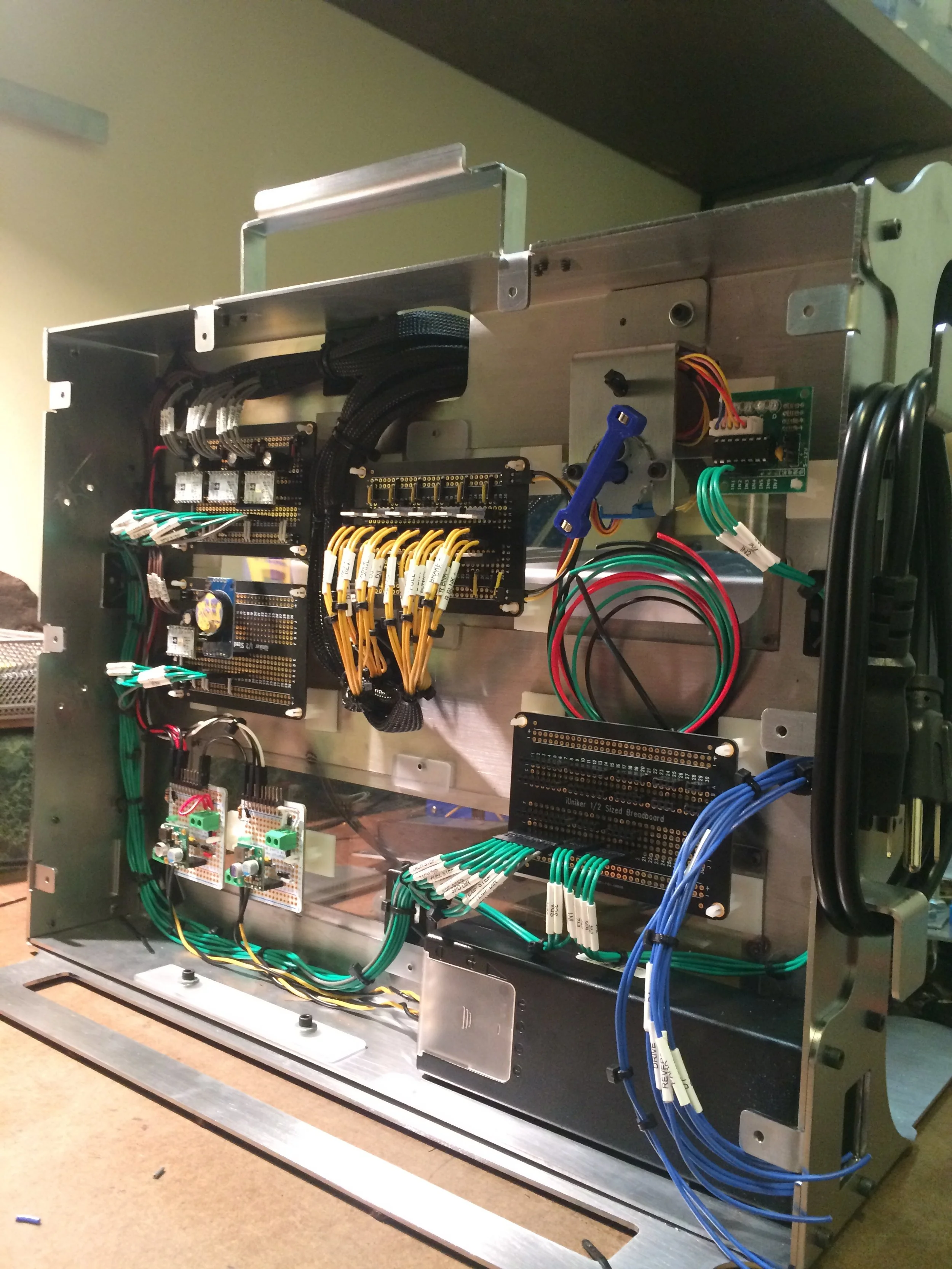
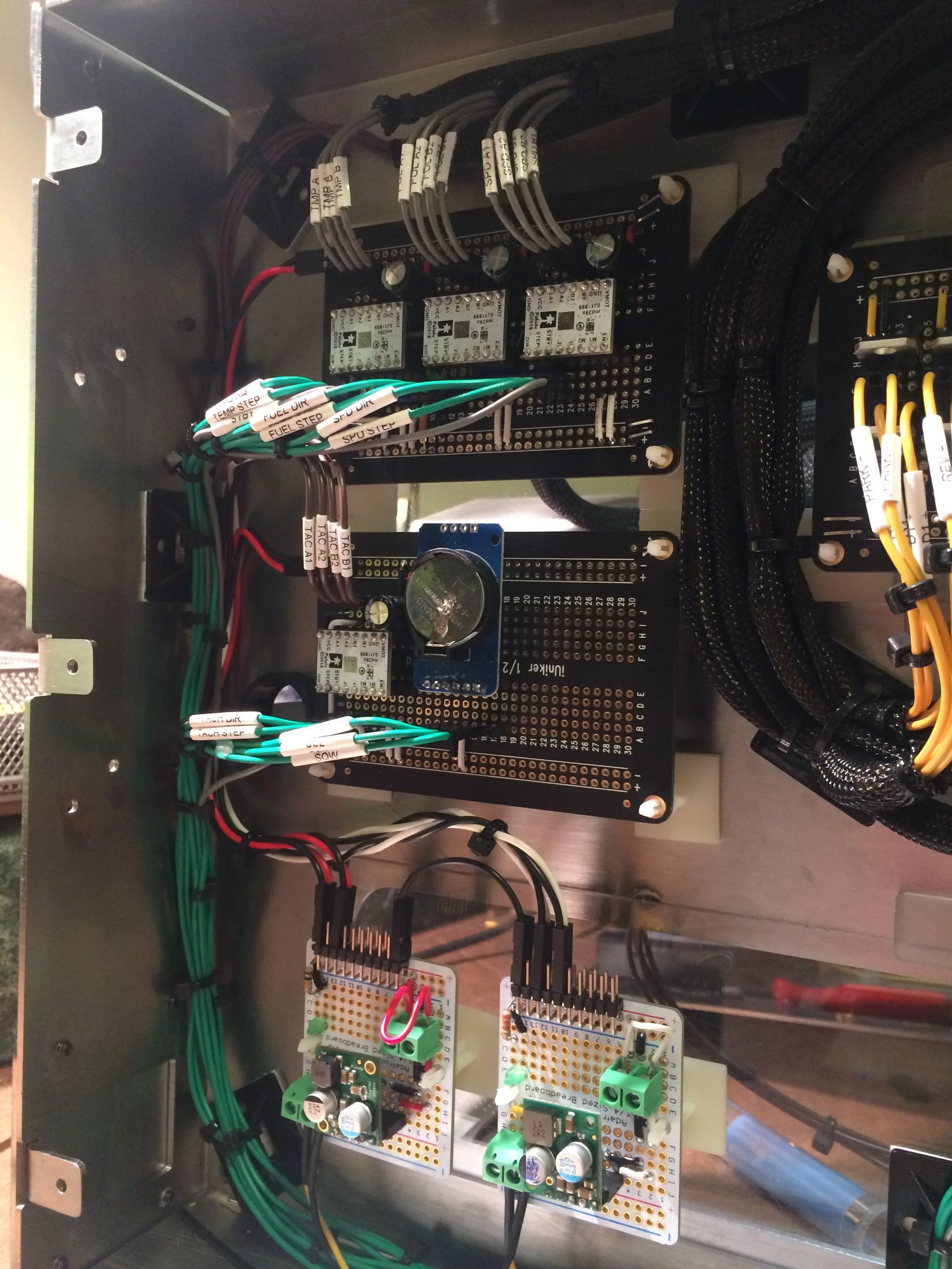
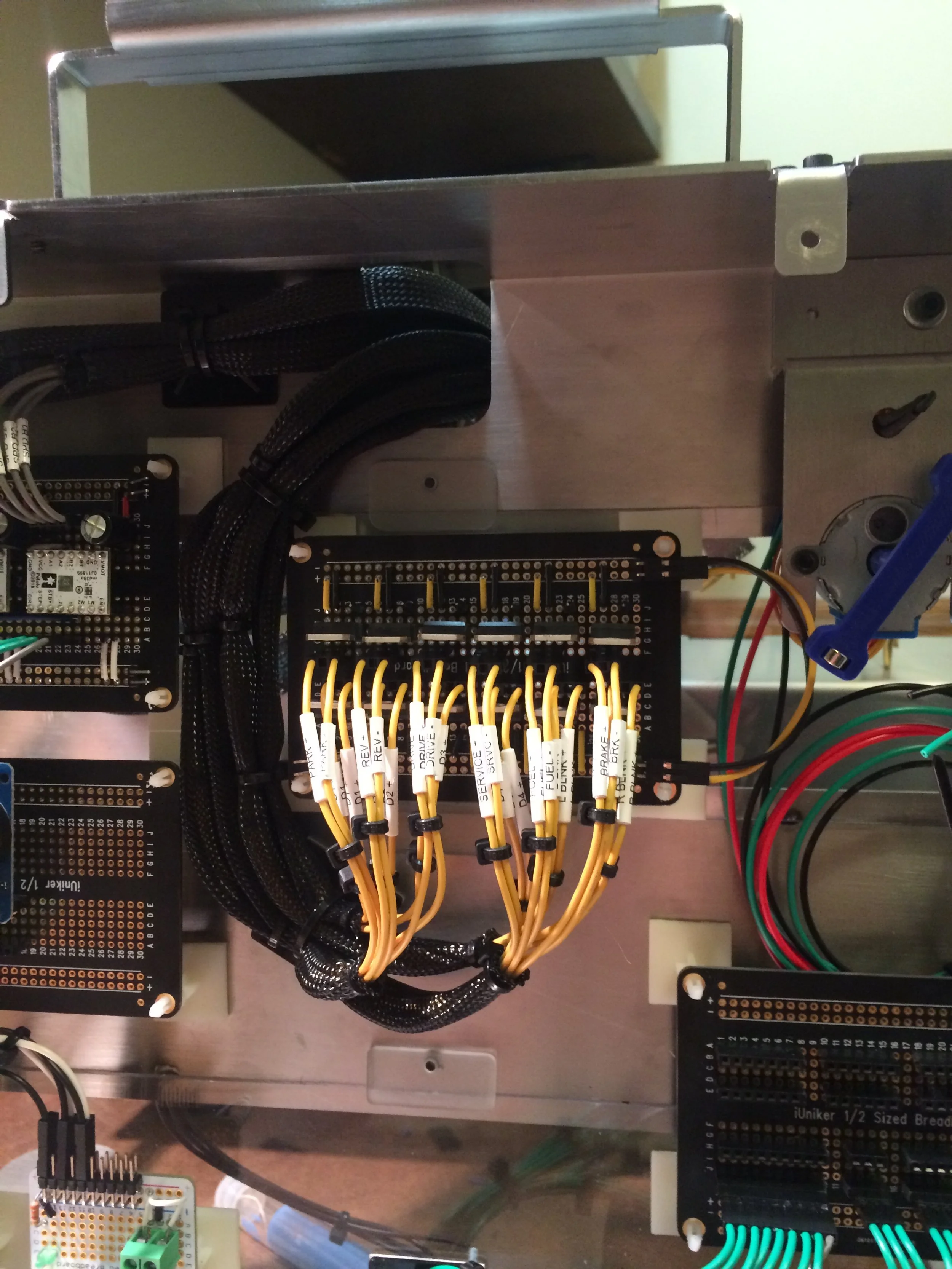
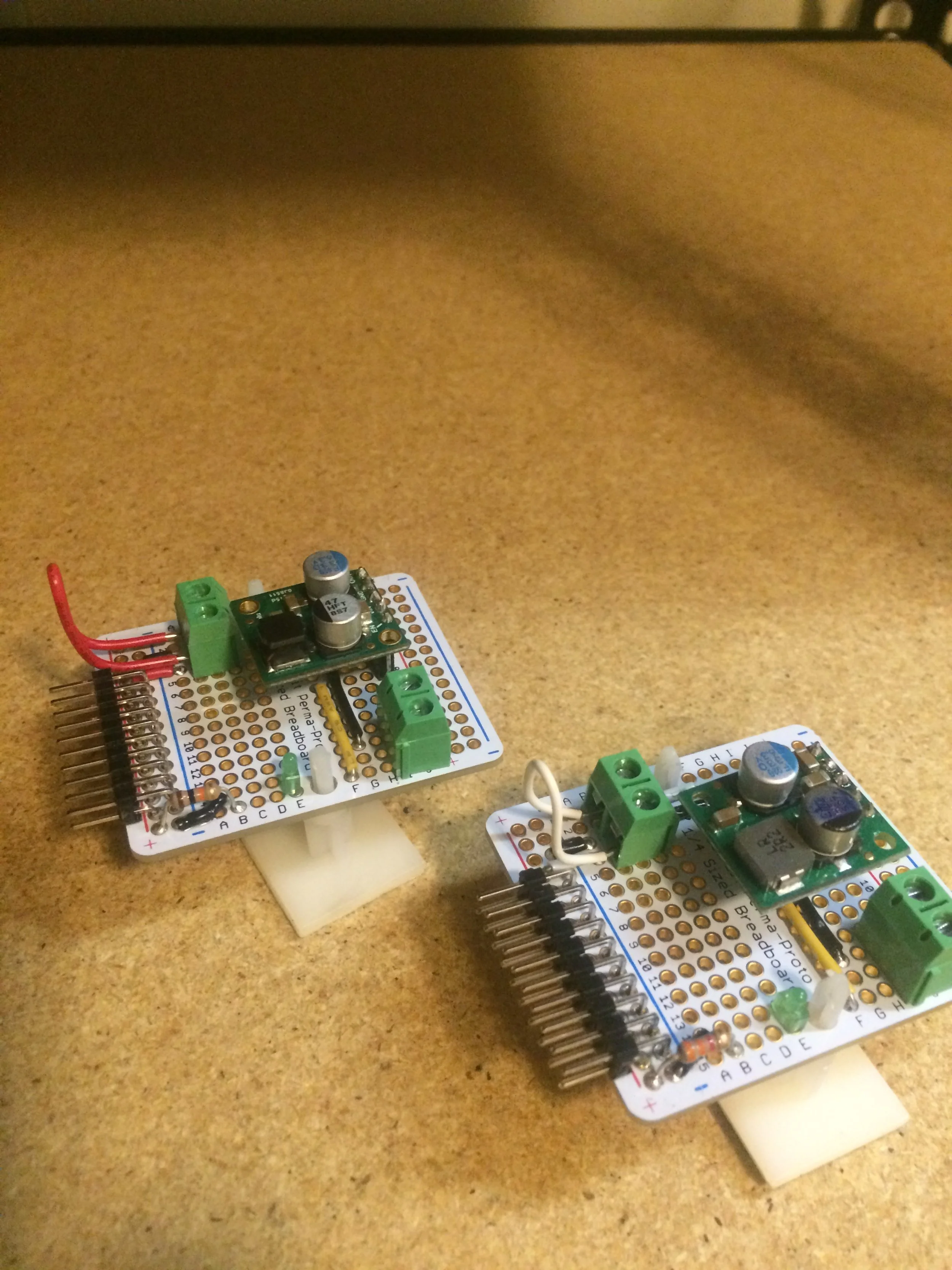
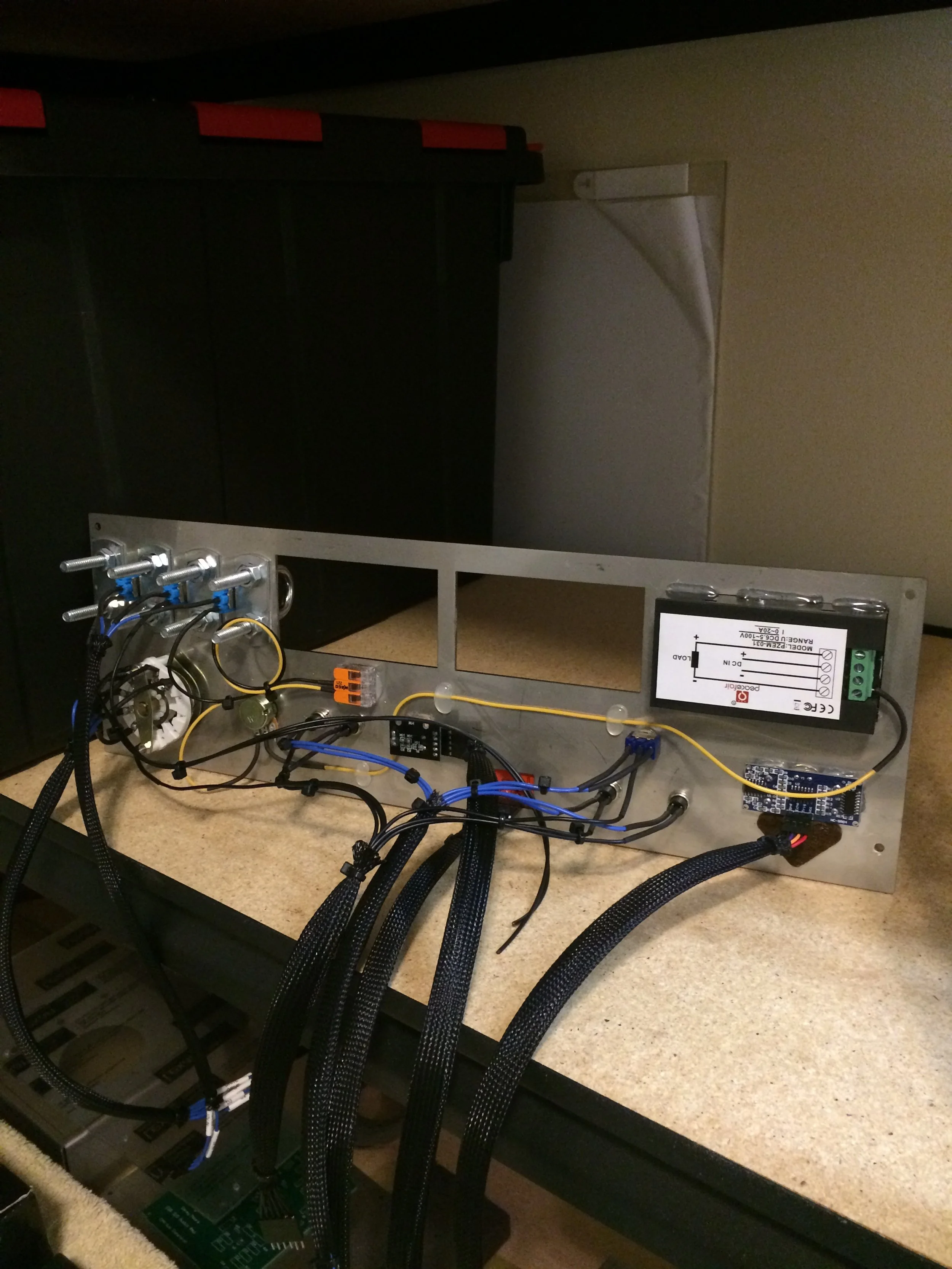
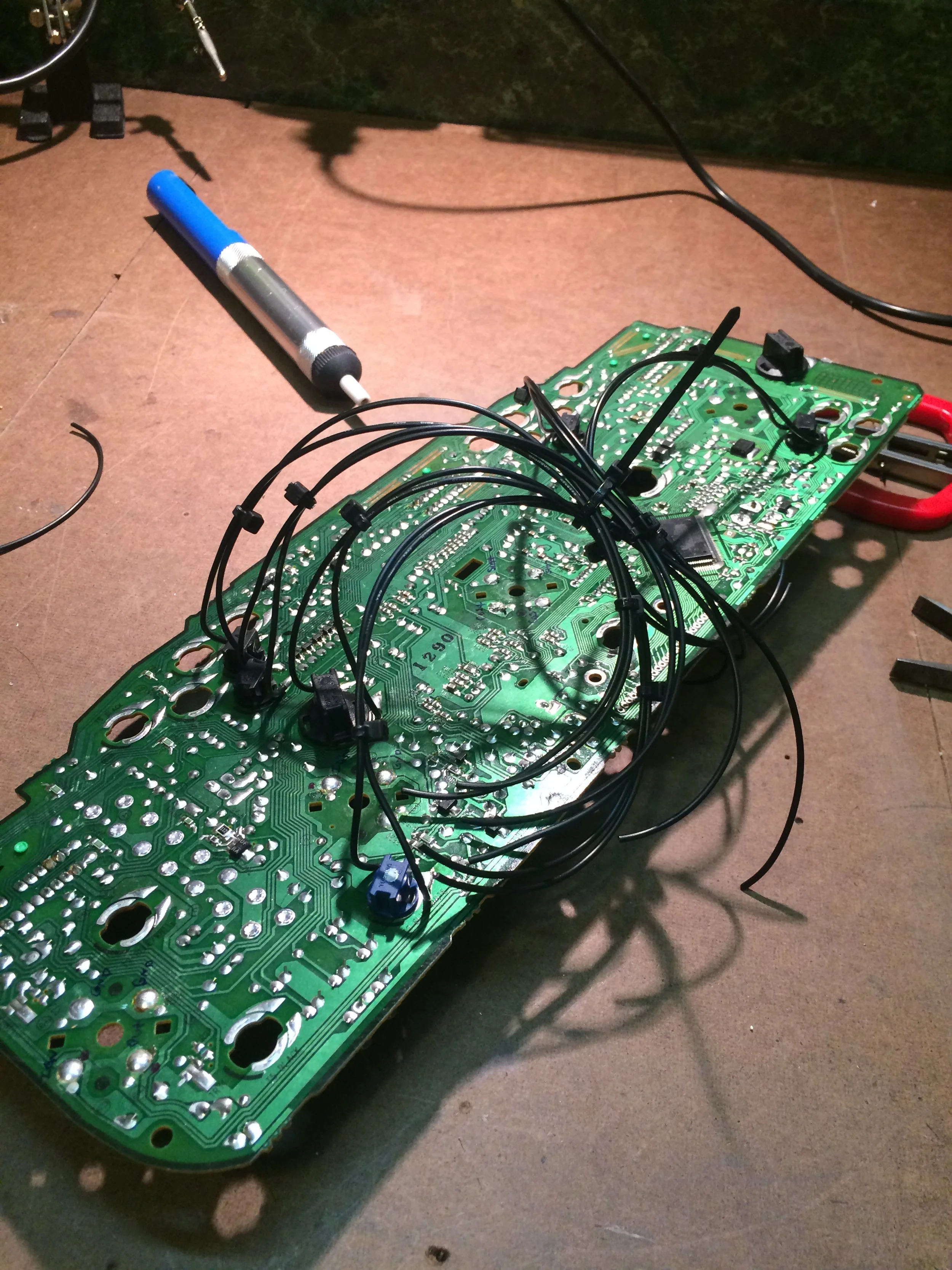
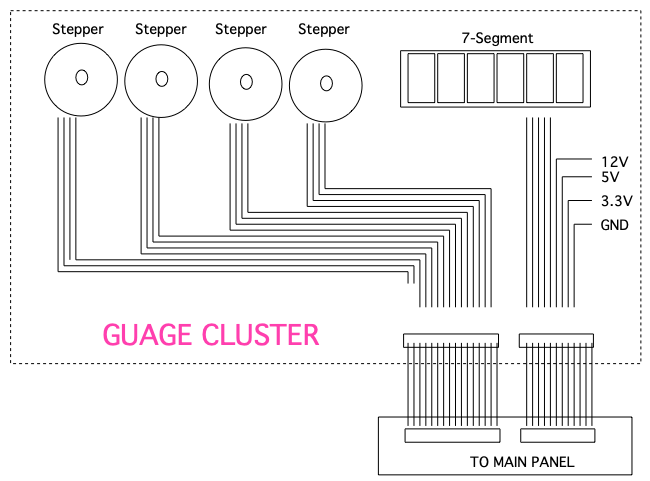
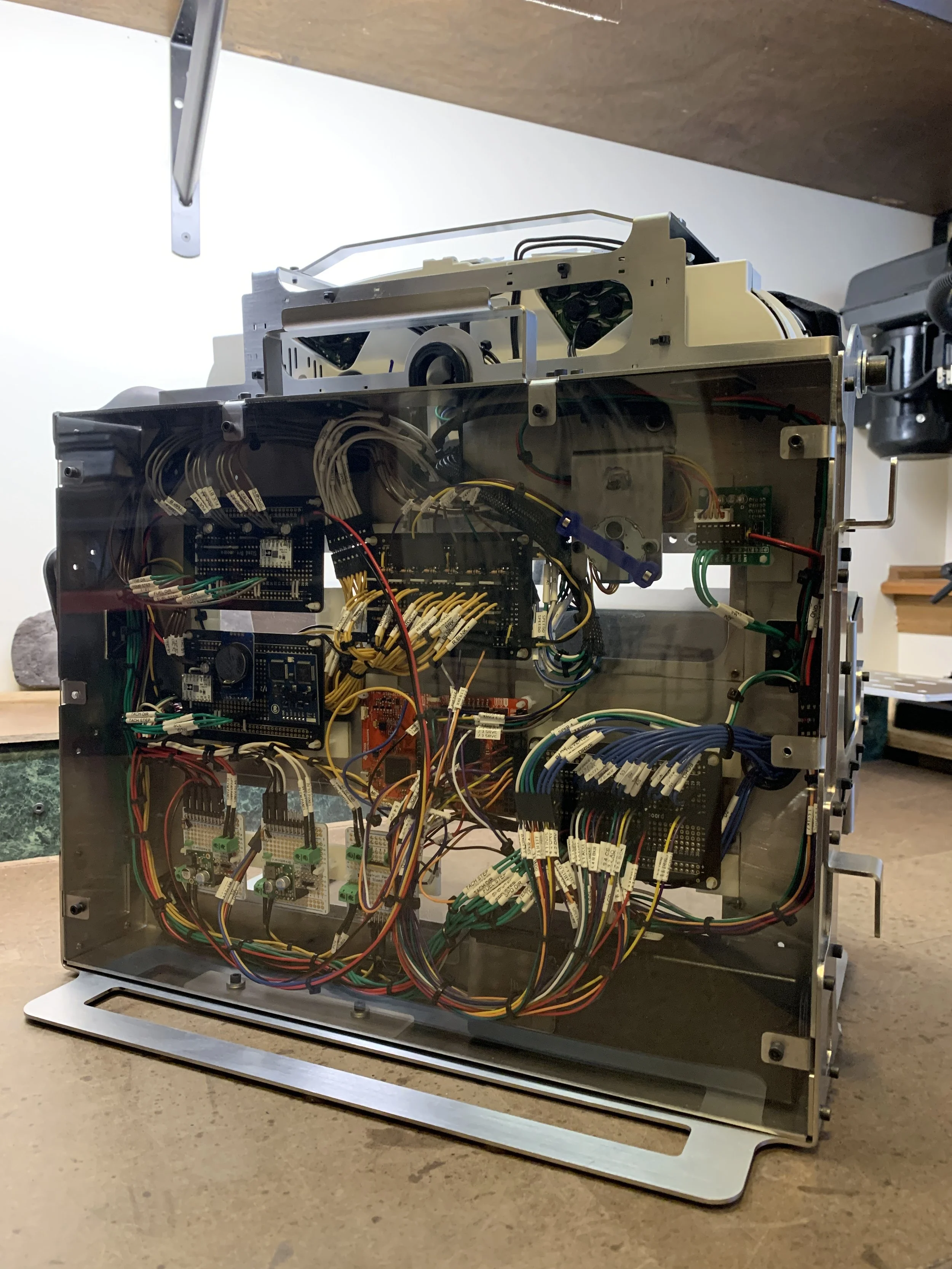
Hardware Design
Pin mapping was vital for organizing the numerous inputs and outputs of the system. Color coding wires along with wire labeling decreased trouble shooting times and made verification much quicker.


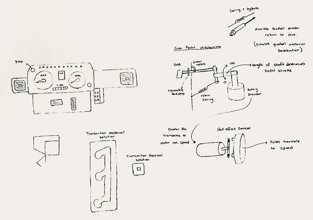
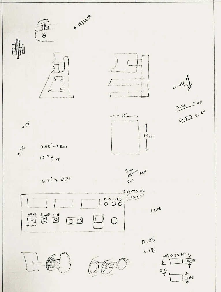
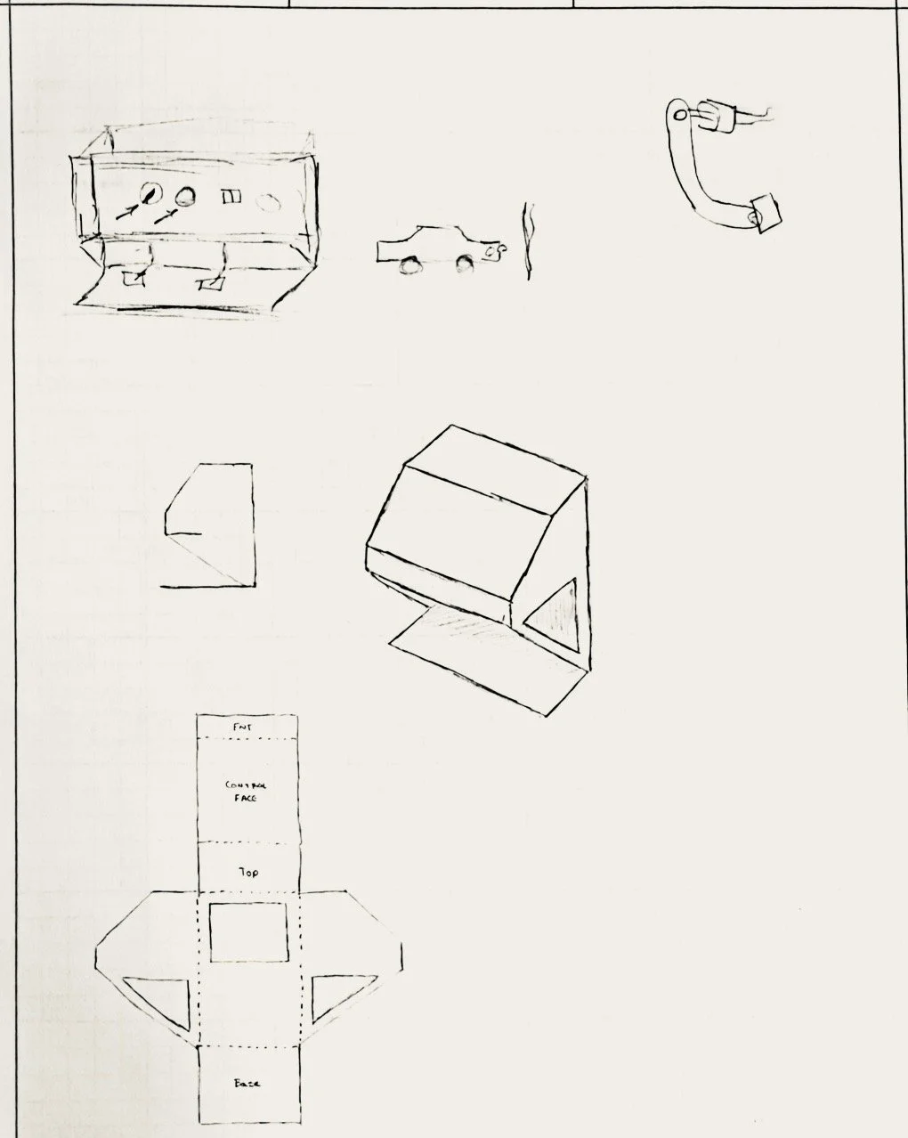
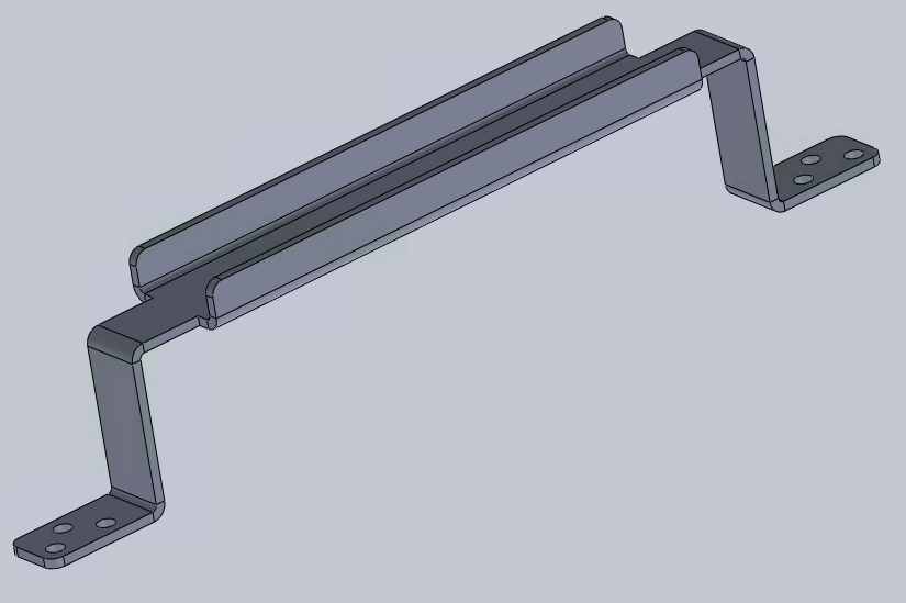
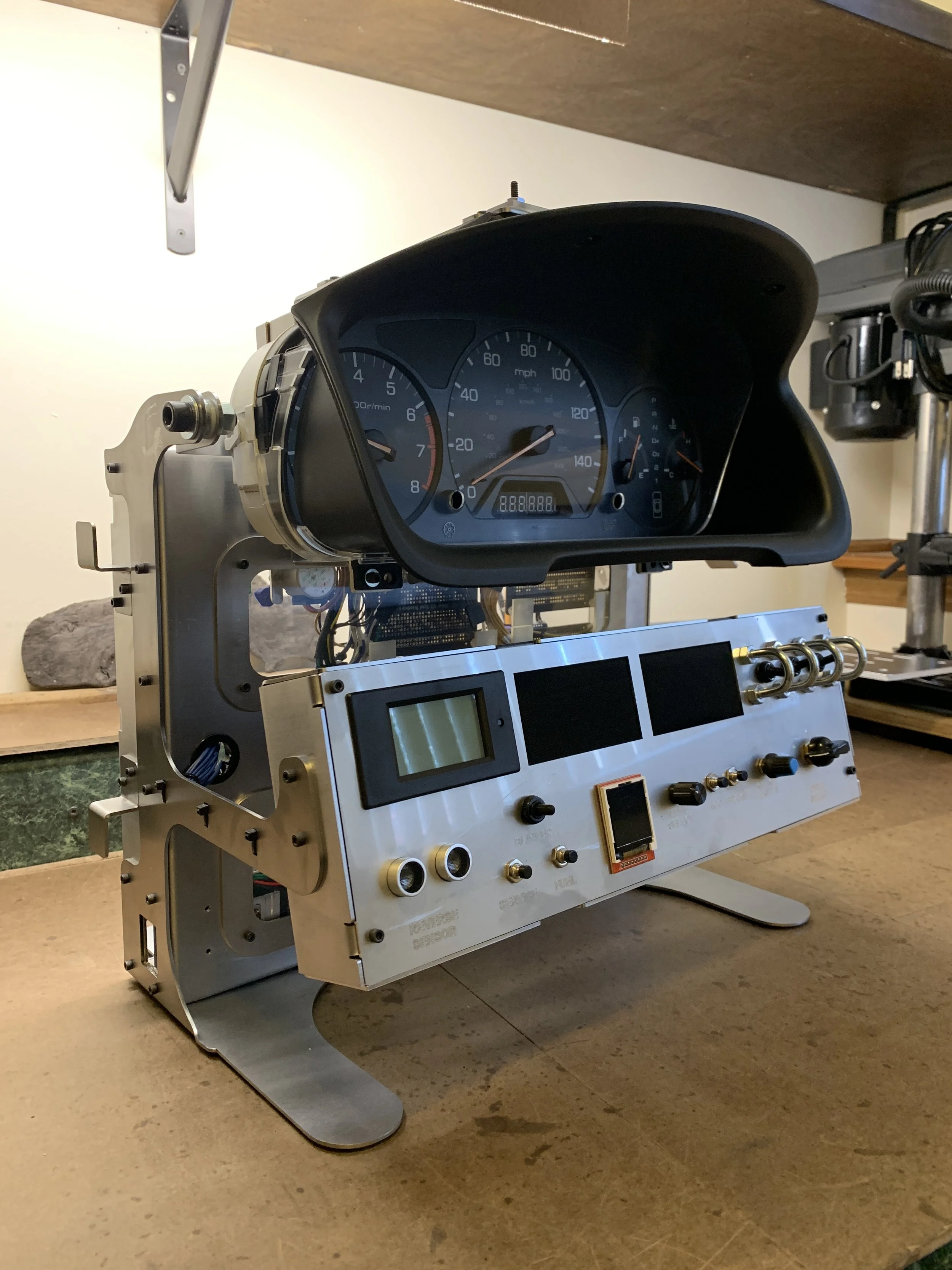
Mechanical Design
The enclosure was designed in SolidWorks and can be broken down into four subassemblies: the frame, electrical box, control panel, and cluster bracket. It features a carry handle, cord management brackets and the ability to rotate the gauge cluster up and down for viewing.


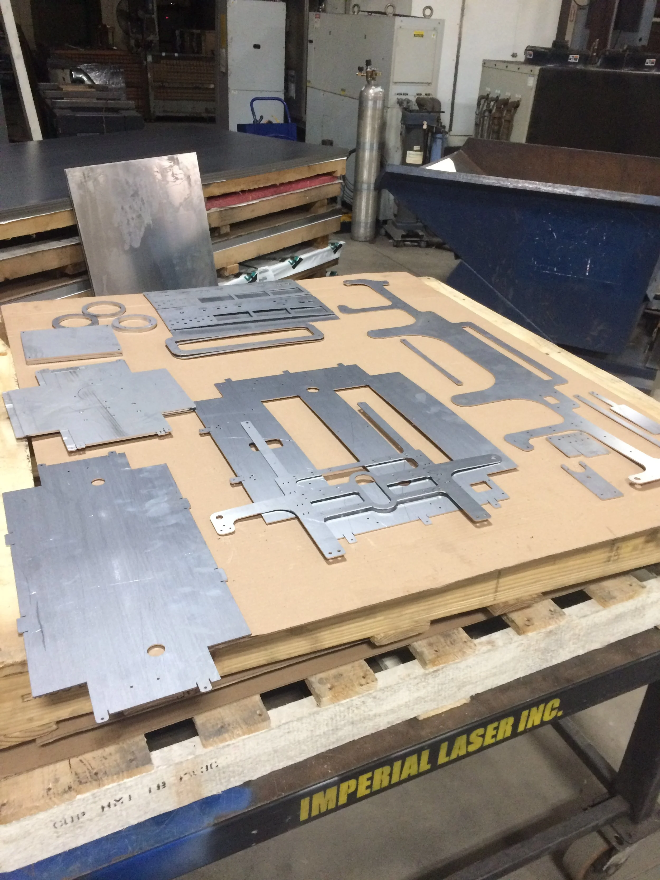
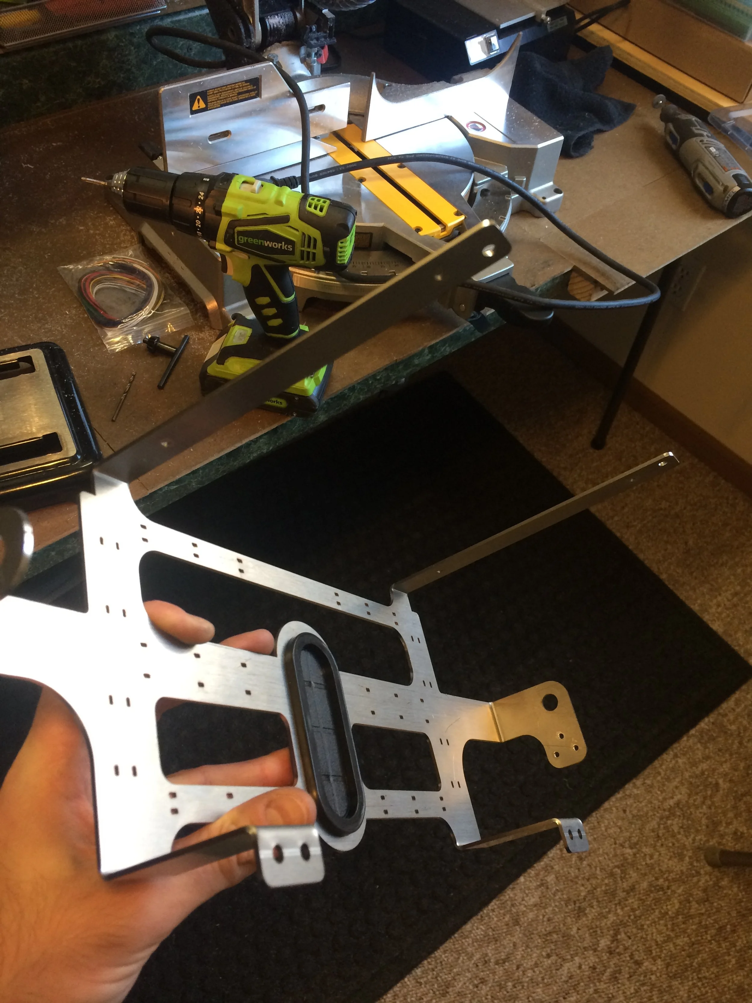
Production / Assembly
The enclosure was laser cut from 316 stainless steel and formed using a press brake. Each subassembly was secured using threaded holes and fasteners. The rear panel was made from clear polycarbonate in order to view the electrical components of the project.
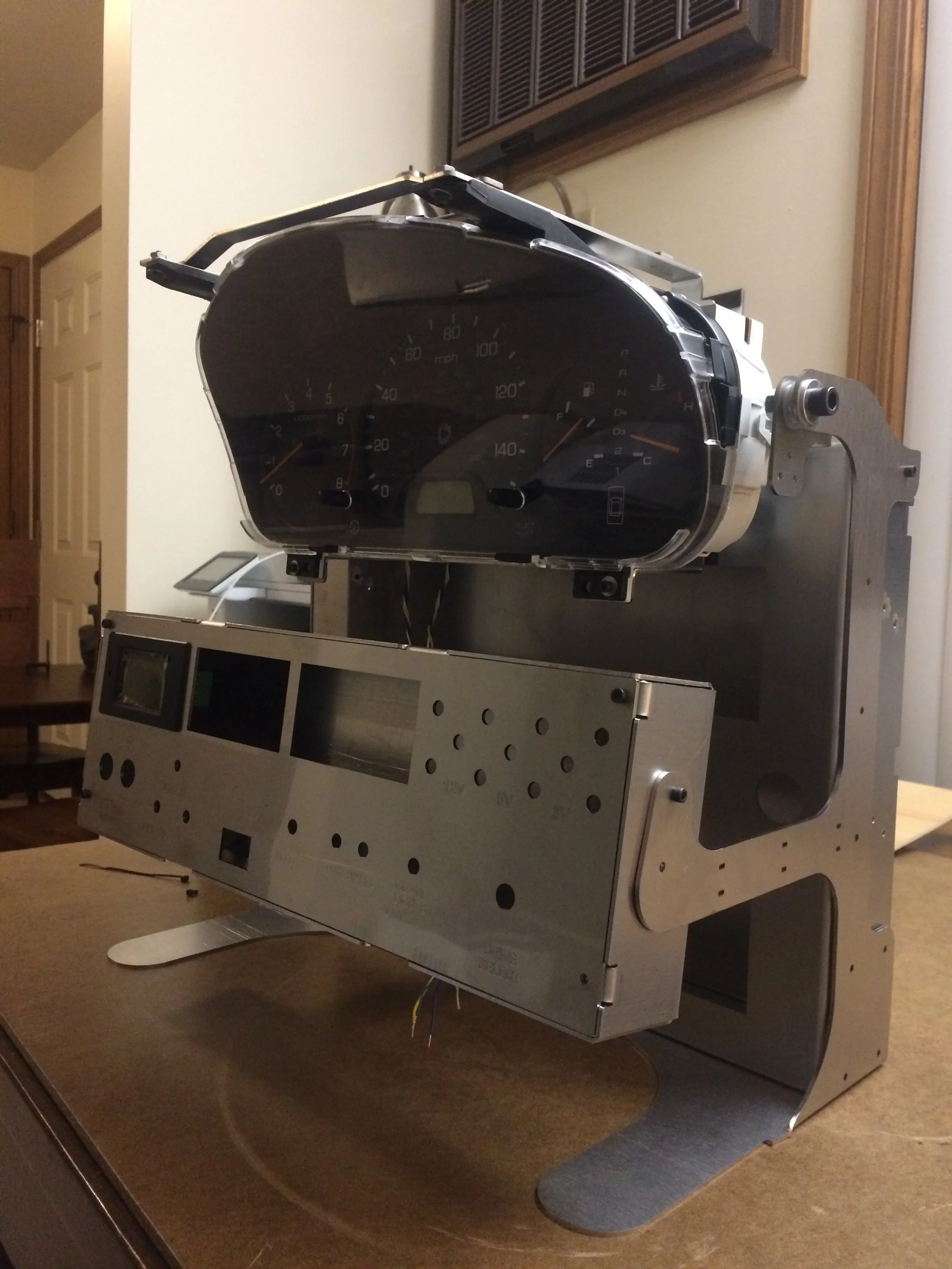
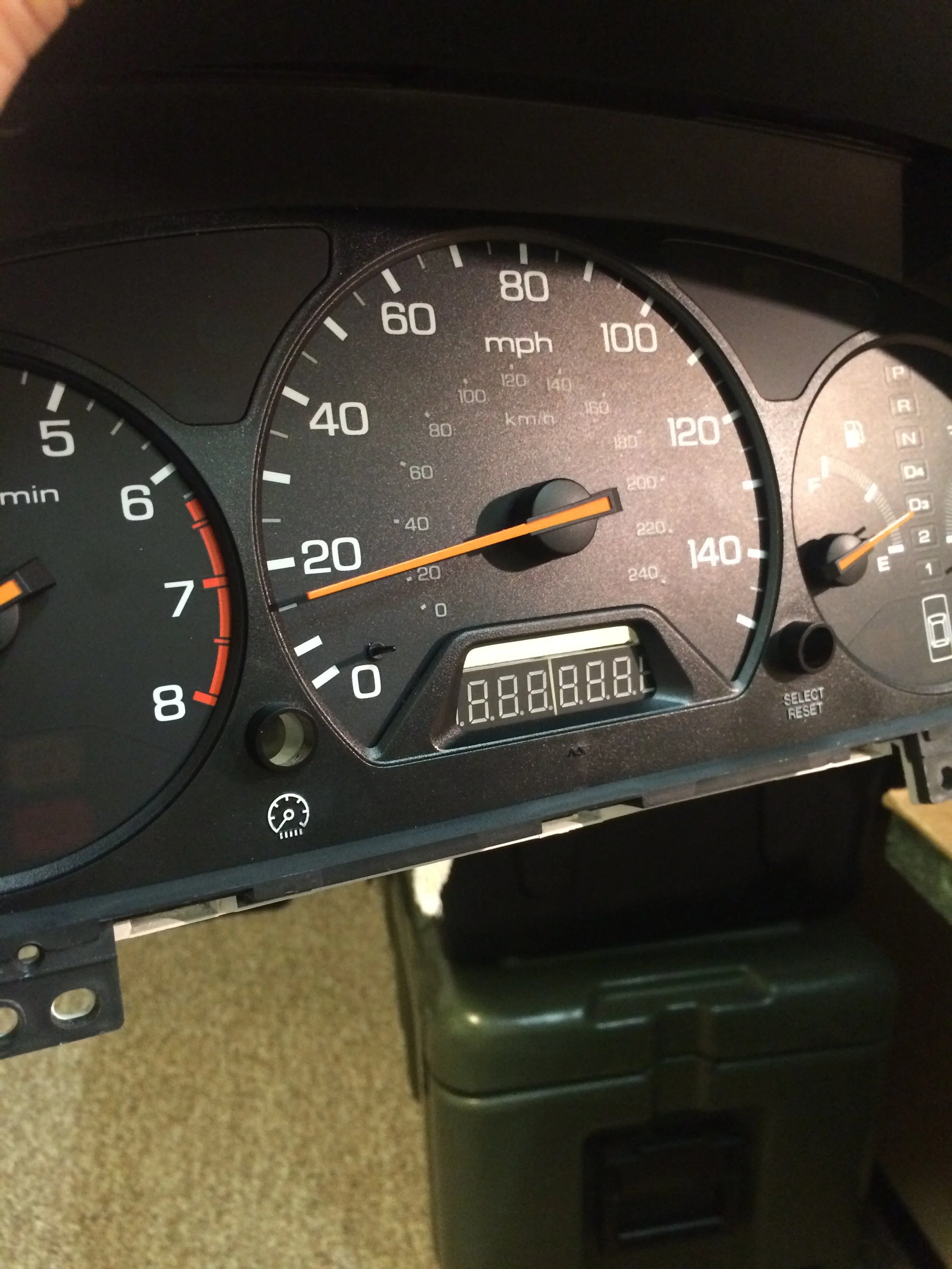
End Result
Videos
Gauge Startup
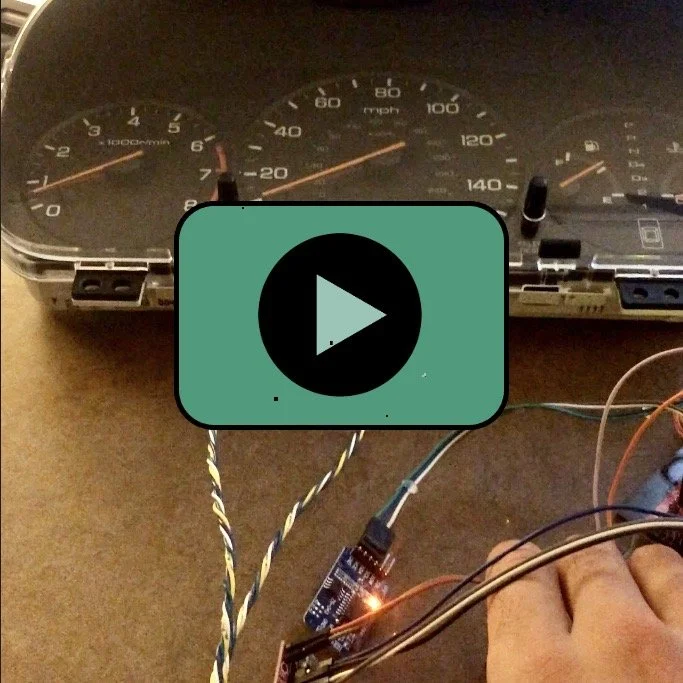
Button Speed Control
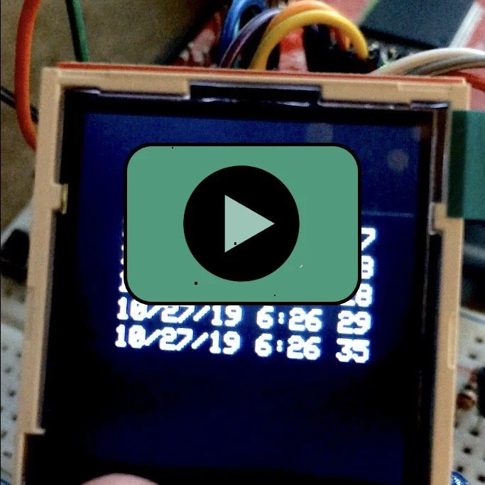
RTC / Fault Screen Testing