Microcontroller Testing Device

Jan 2022 - Aug 2022
Overview
A Capstone project requiring the design and production of 10 devices capable of testing the hardware components of Arduino and STM32 microcontrollers. Funded by GVSU’s Engineering Department, this tool allows 1st and 2nd year engineering students to quickly check the health of their development boards.
-
There are several engineering courses where students are required to program and build hardware circuits with their microcontroller. Hardware connections made incorrectly can destroy or damage individual pins and in some cases the entire board. Additionally, some boards are damaged before being used by the student.
Students and professors often have the need to identify whether unusual behavior is hardware or software related in embedded system projects. Oftentimes, it can be quite cumbersome to diagnose hardware related issues that may occur on a microcontroller, such as damaged GPIO pins, voltage regulators, and other critical hardware peripherals. This presents a need to find a more expedient way to diagnose these issues when many students may require help.
This project will solve this problem by checking the functionality of the Arduino Uno and STM microcontroller hardware through a series of hardware tests. This will allow students and professors to confirm hardware faults or rule out any hardware errors thought to be causing issues. If hardware is not behaving properly, the device created by this project will display the hardware failures on a Graphical User Interface. Otherwise, the student or professor can assume their issues to be coming from software.
-
Team Captain:
Hosted meetings
Set goals and timelines
Distributed work loads
Tracked and reported progress
Tracked Budget
Ensured the team had every resource needed to be successful
Mechanical:
Overall design
Material selection
3D printing
CNC machining
Part tracking
10 Unit production run
Electrical:
Cable selection
Building wiring harnesses
Software:
Contributed to the development of the software architecture
Misc:
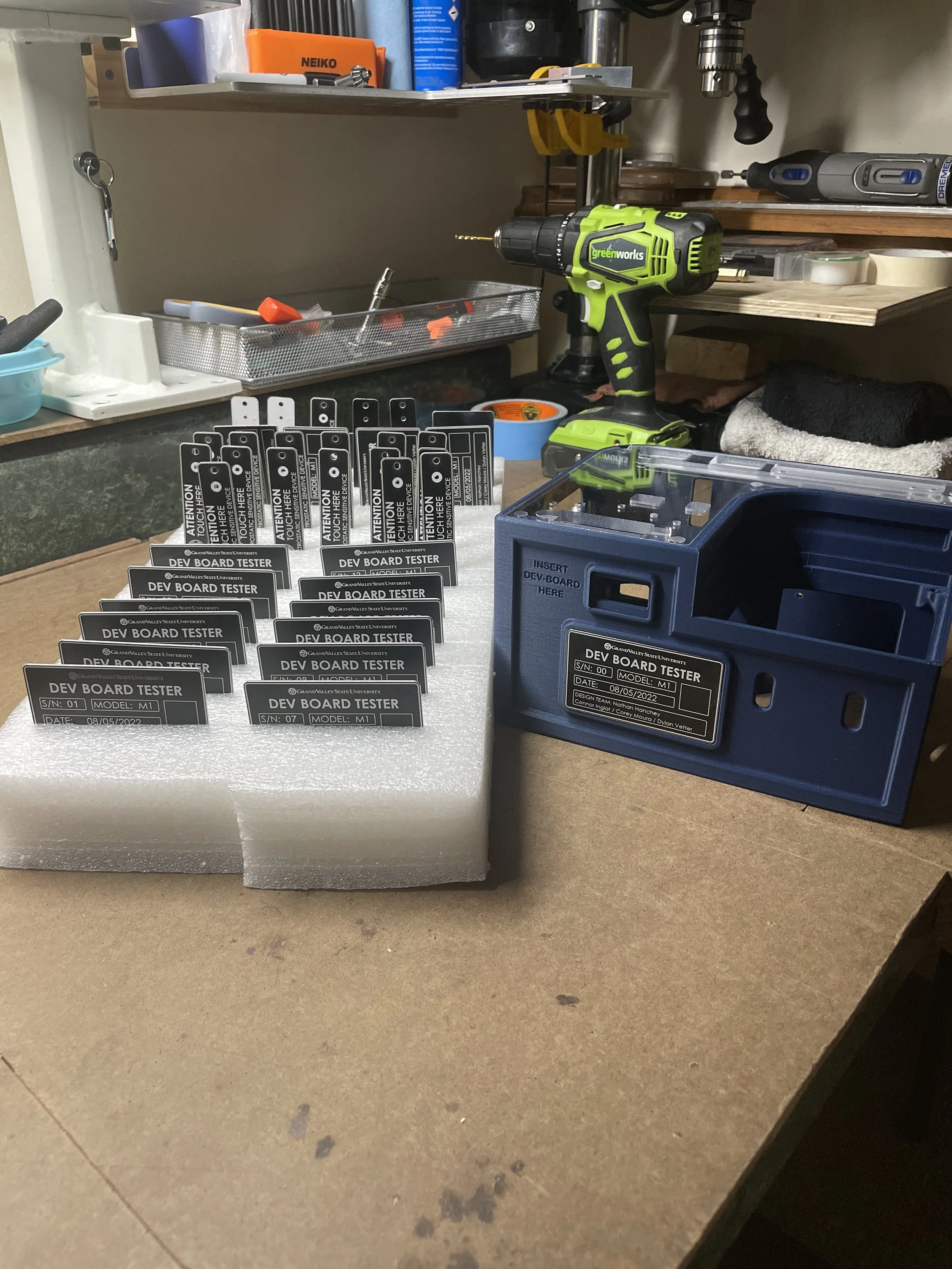
Laser cut and etched ESD grounding plate & front placar
-
Lessons:
A leader must accept full responsibility for their teams failures. And in success, must claim little to no credit to themself, but attribute the success to the members of the team, their talents and efforts.
Outcome:
This was a fulfilling project with many challenges. One of the challenges being the absence of a mechanical engineering teammate. Another challenge was managing the budget durring the pandemic and part sourcing. Realizing this difficulty, we began our part sourcing early and across various vendors to fulfil our needs. The drawback to this was paying shipping on every new order. To offset some of the added cost, we chose to do as much in house production as we could including populating all 20 PCBs and 3D printing aproximatly 300 parts.
Overall, the team stayed on track though the 9 month project cycle, hit all milestones, completed all assignments on time, and maintained a productive and professional relationship with our sponsor and client.
↓↓ Photos ↓↓
Ideation
During the pandemic and the period immediately following, cost and resource availability were significant concerns due to supply chain shortages. This required us to work with the client to determine realistic expectations while still fulfilling core requirements in areas such as ease of use, portability, cost, robustness and scalability.


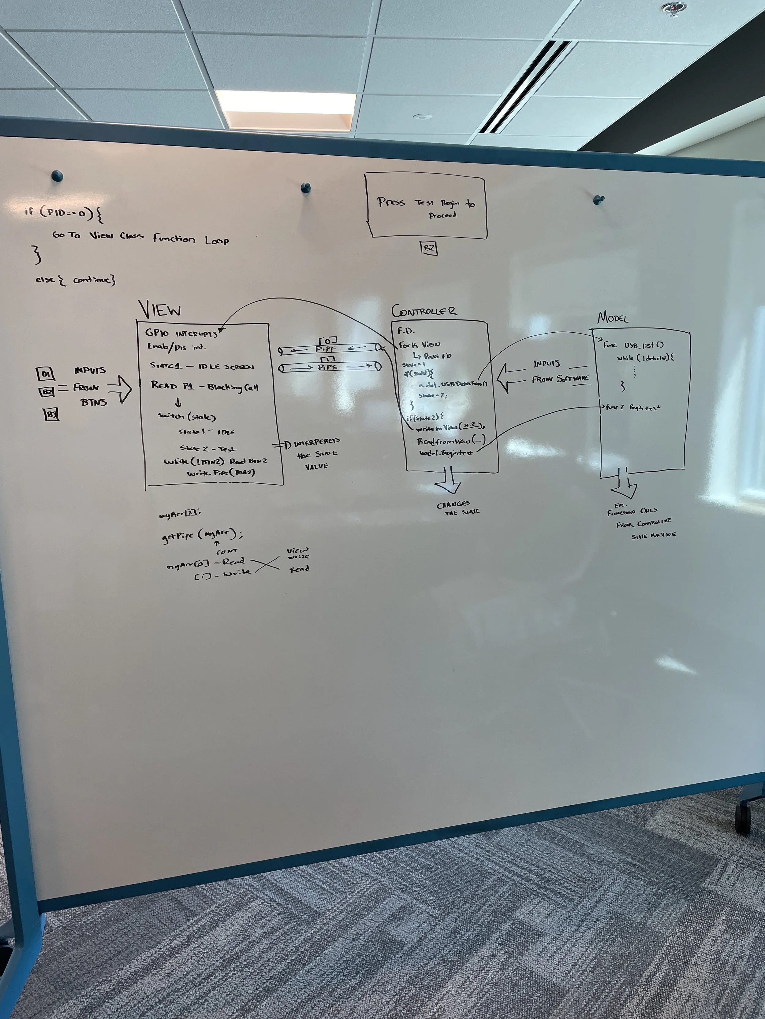
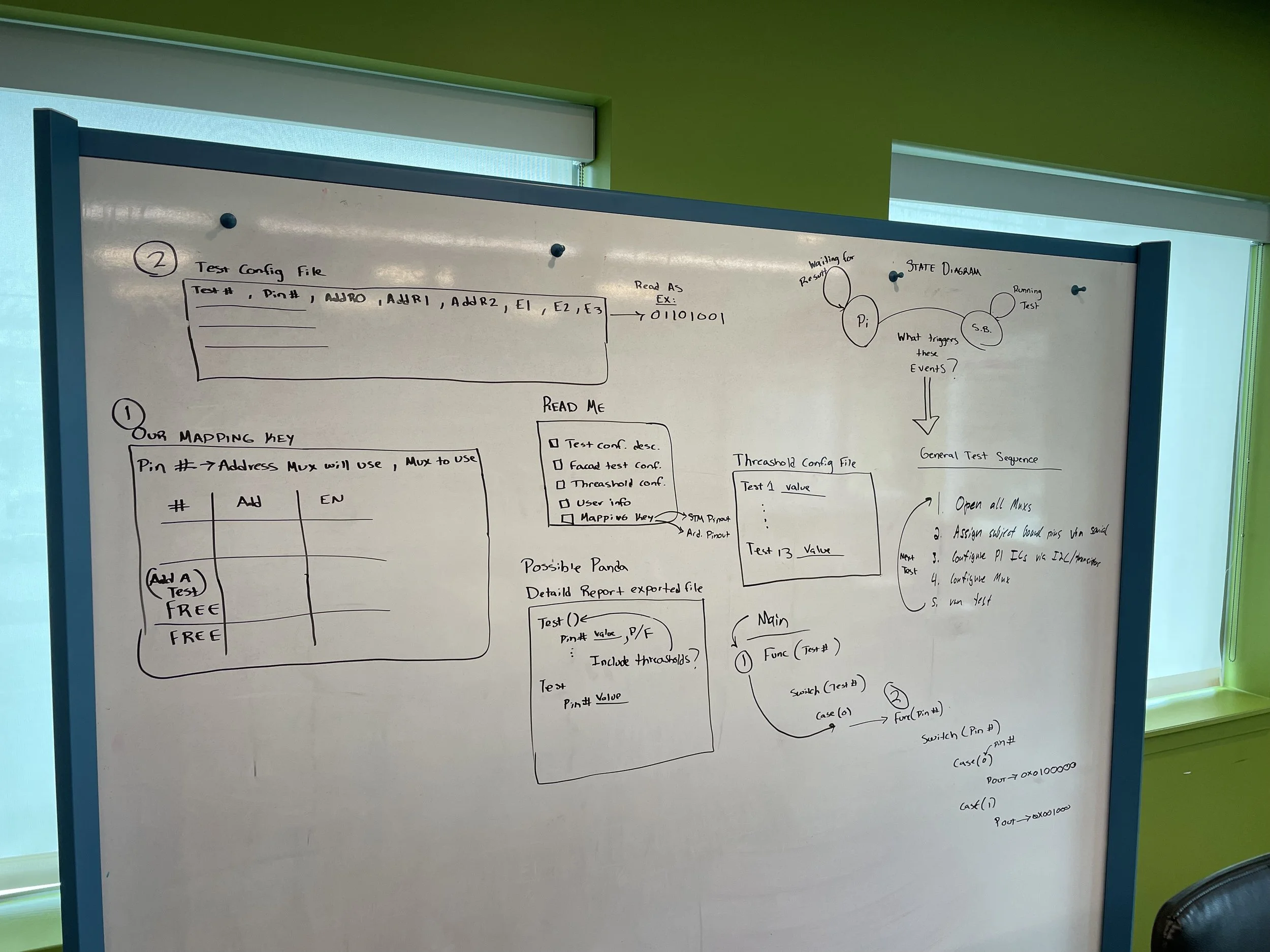
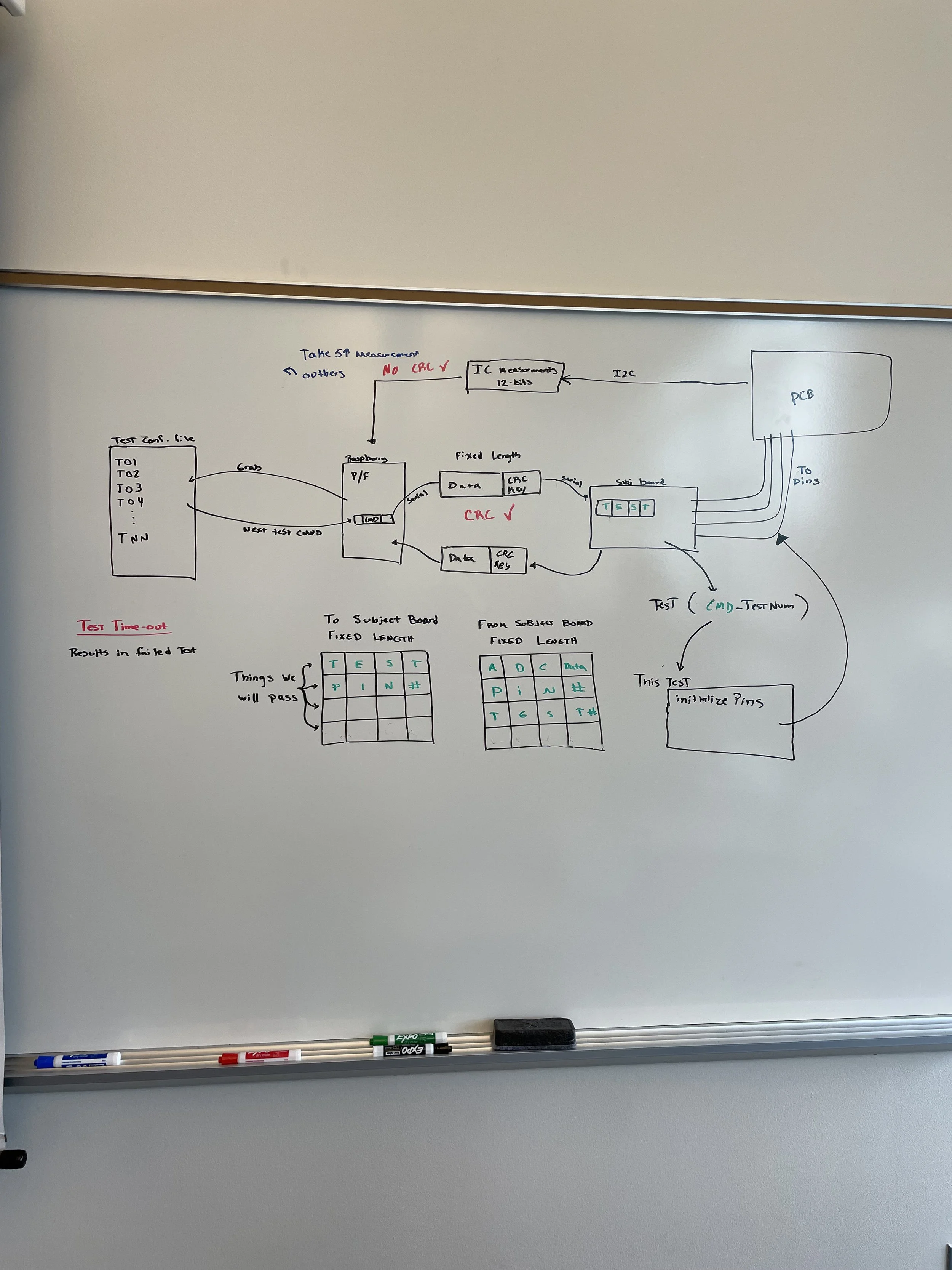

Software Design
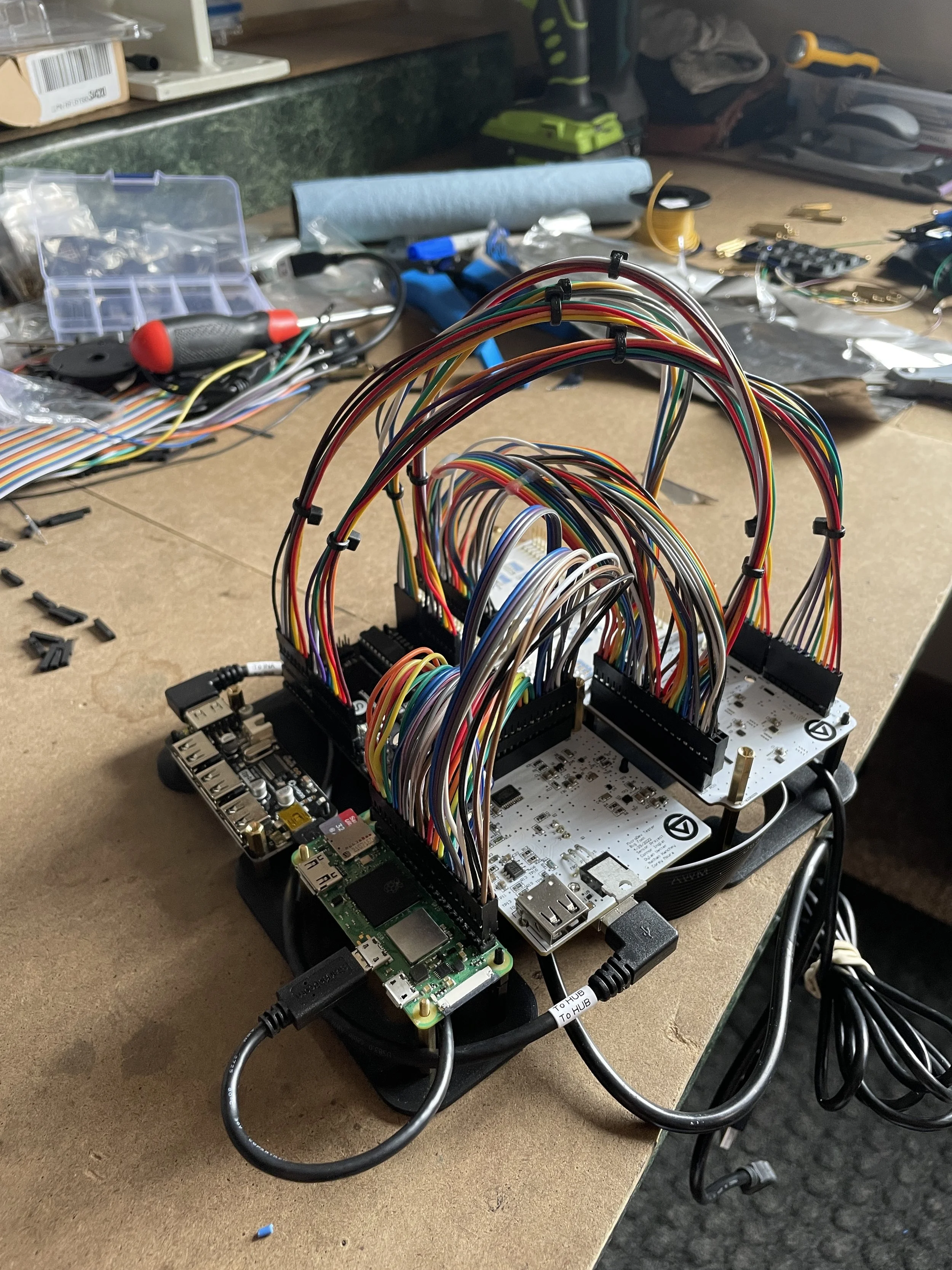
Two programs were designed to control the testing process. The first program runs on a Raspberry Pie, sends testing criteria to the subject board and controls the GUI. The second program is flashed onto the subject board when testing begins and sets pin configurations for each test. Serial communication is used throughout testing to coordinate between the device and subject board.
Software User Manual (not written by me)


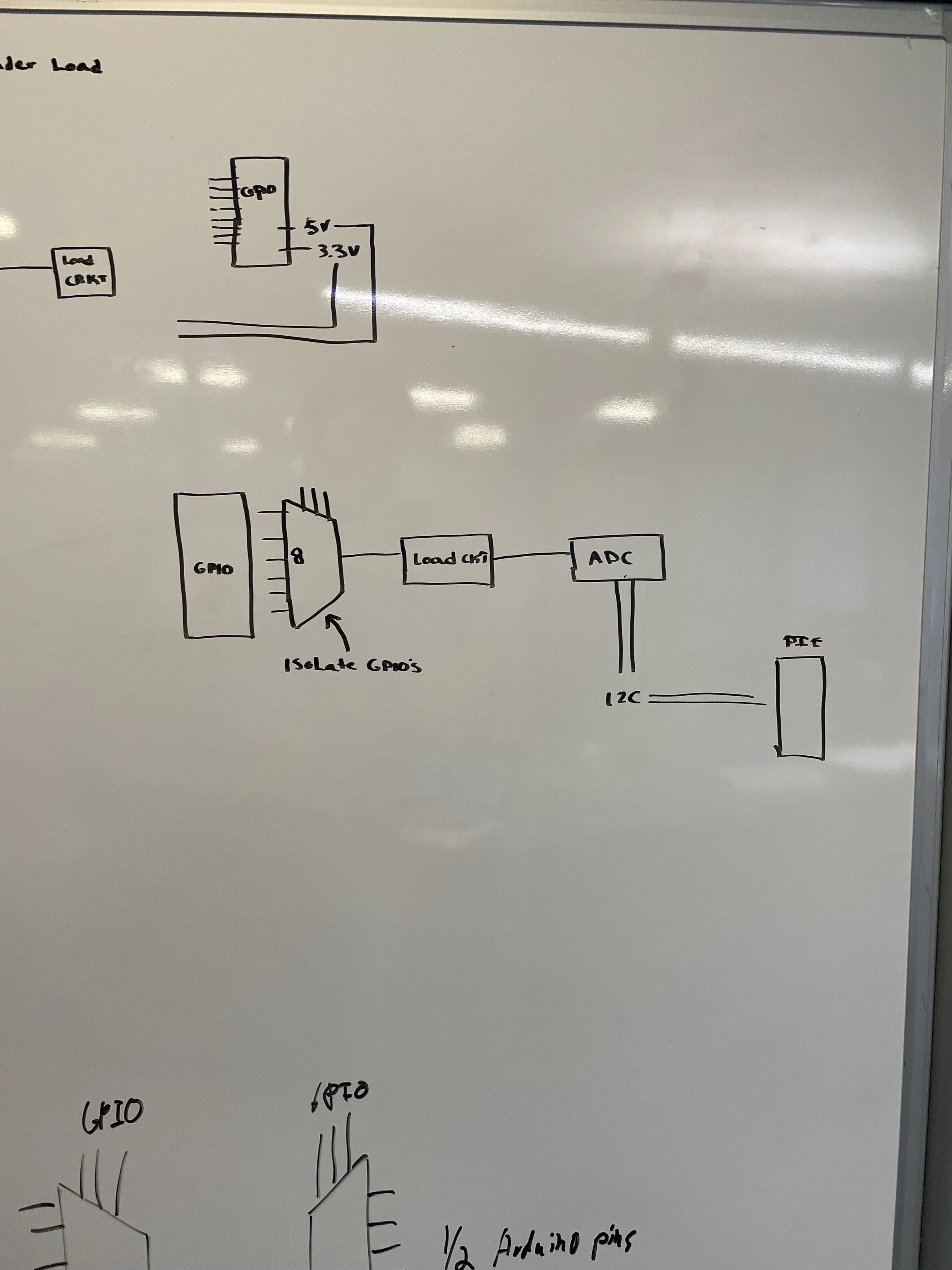
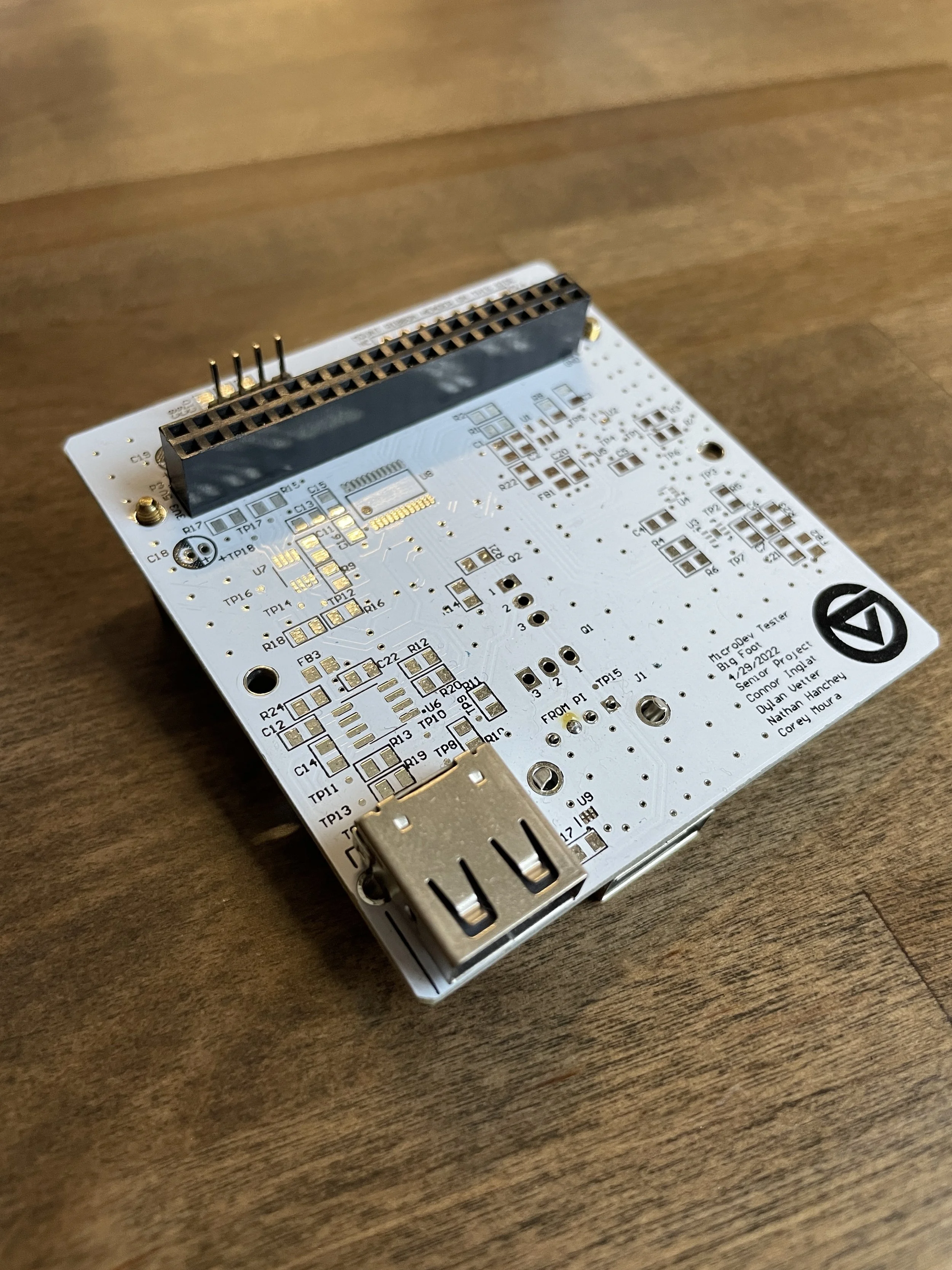
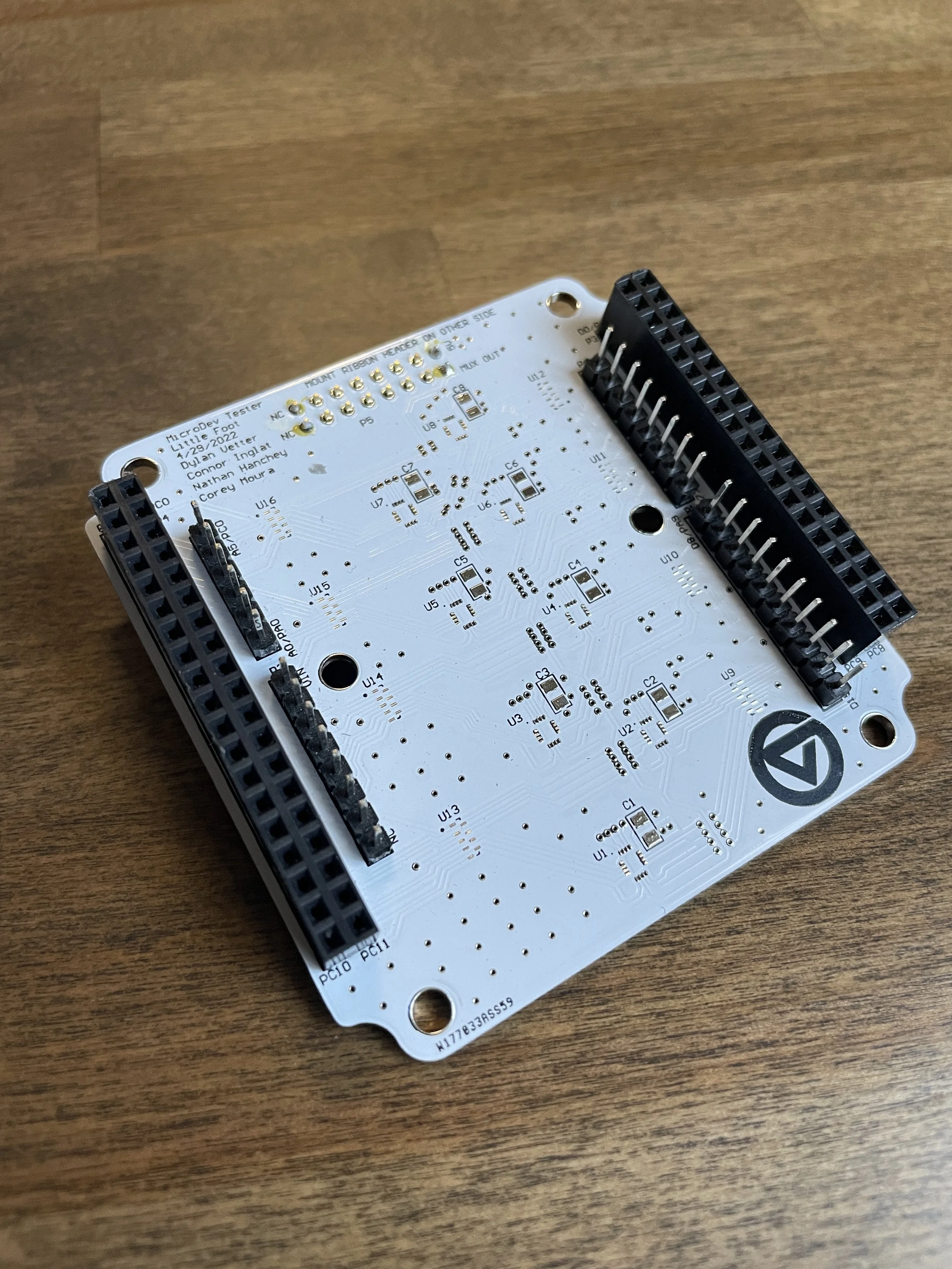
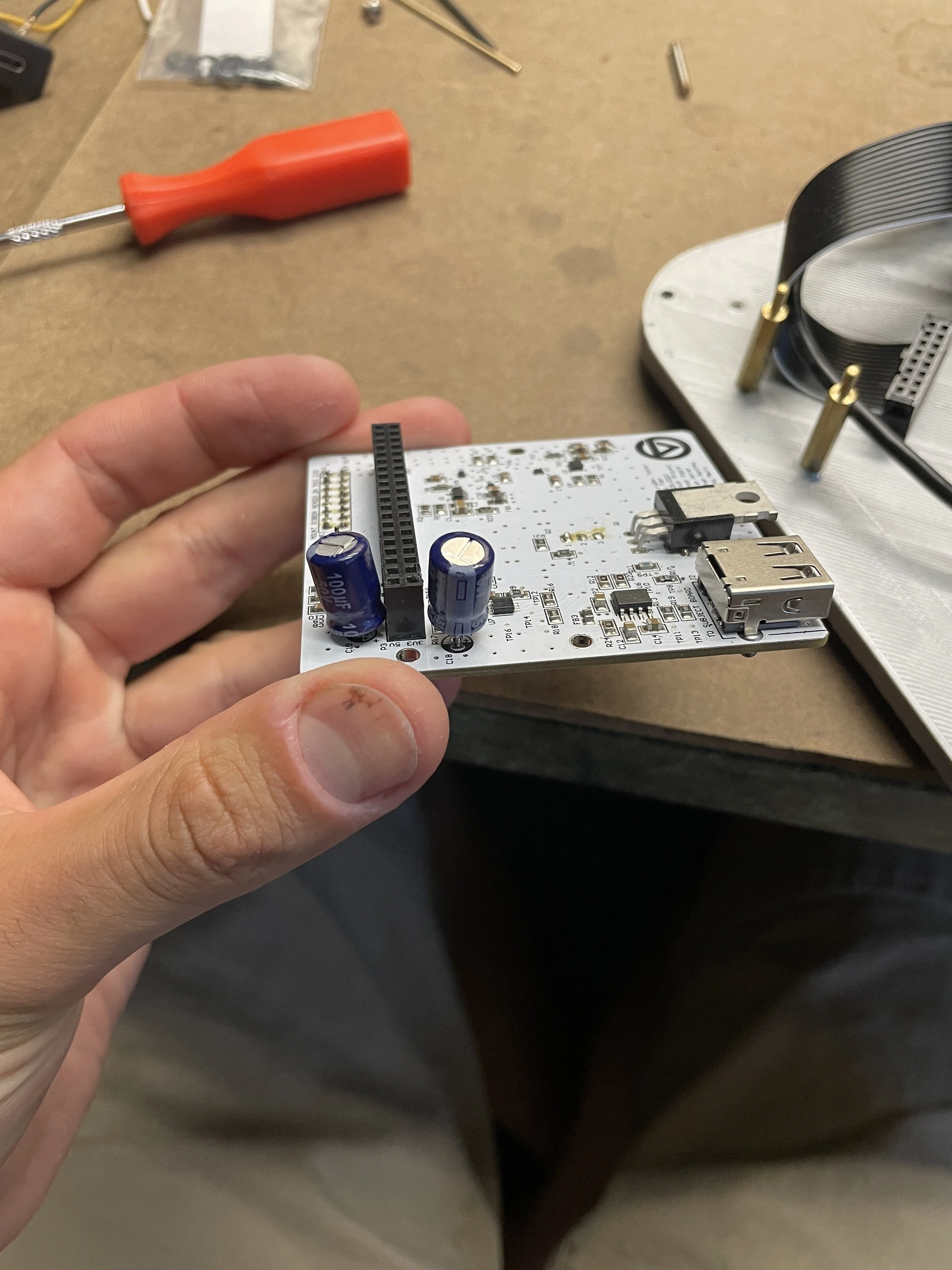
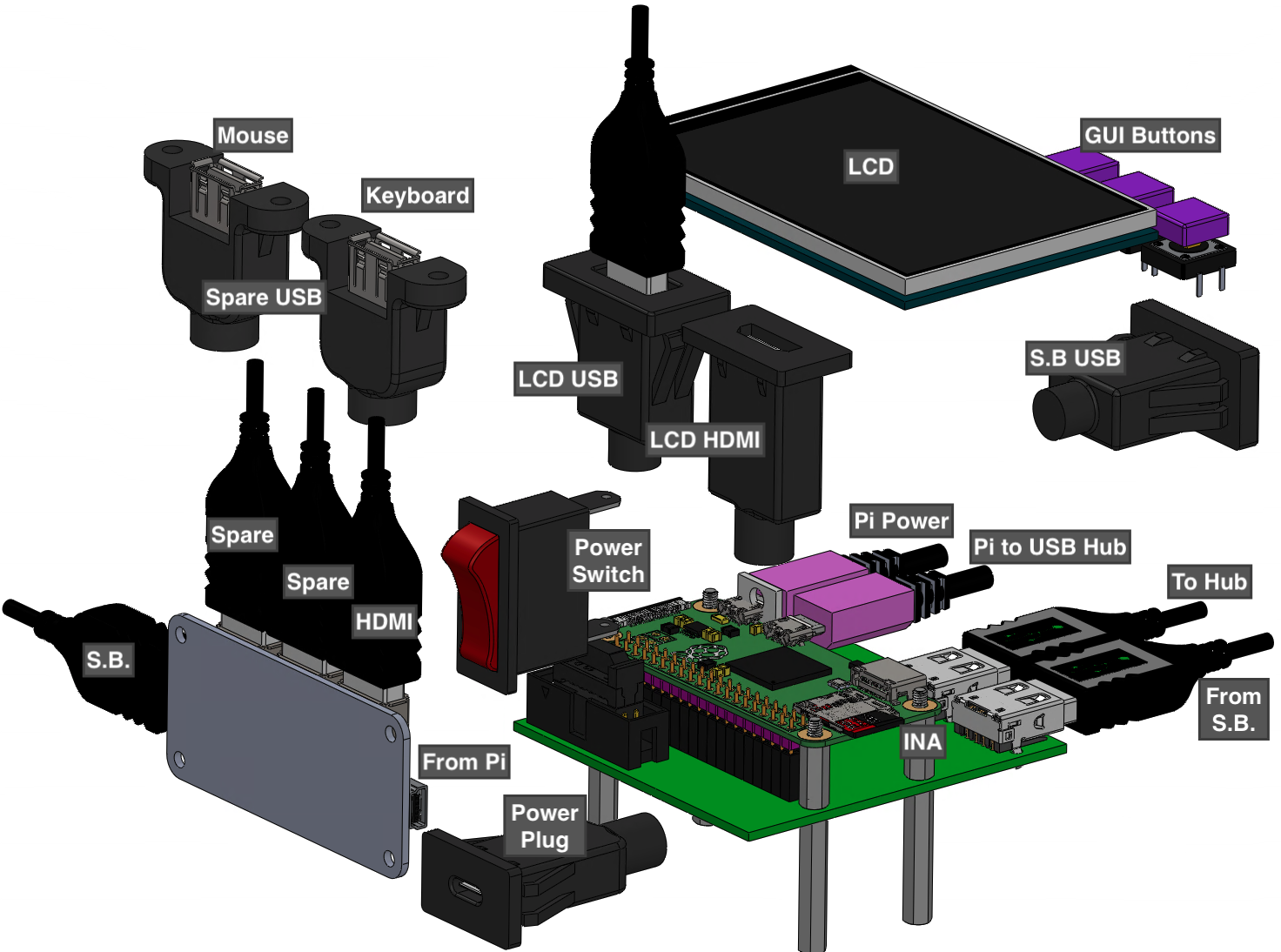
PCB Design
Two PCBs were designed for the device and work together during testing. The Little Foot PCB provides a physical interface between the device and subject board and houses the multiplexors used to isolate pins during testing. The Big Foot PCB is connected to the Raspberry Pie and contains the ADC, DAC, and INA ICs used for measuring pin outputs.


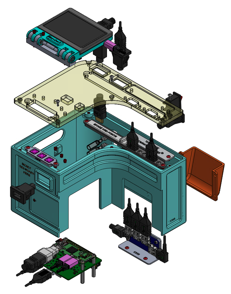
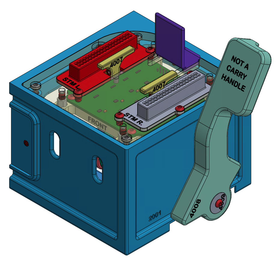
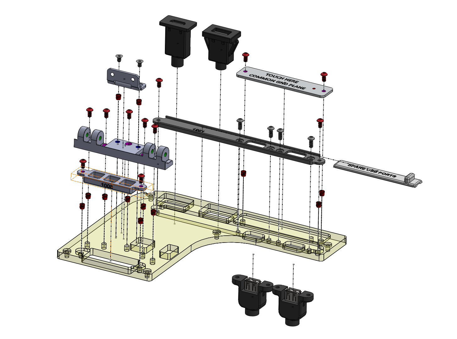
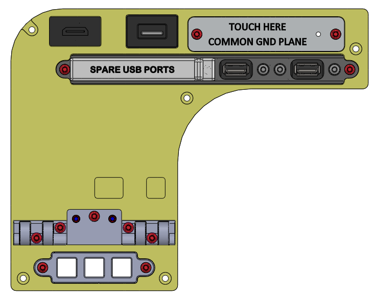
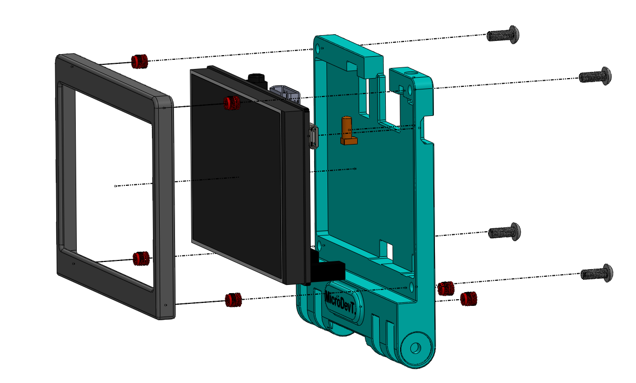
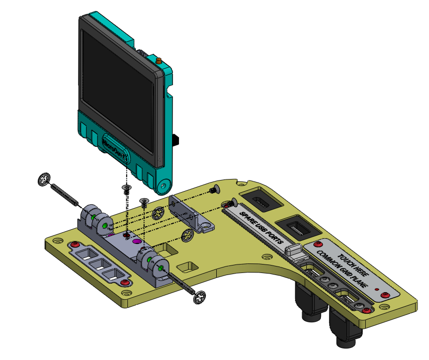
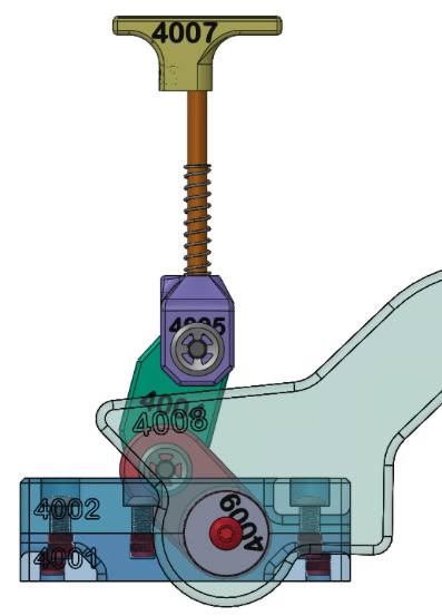
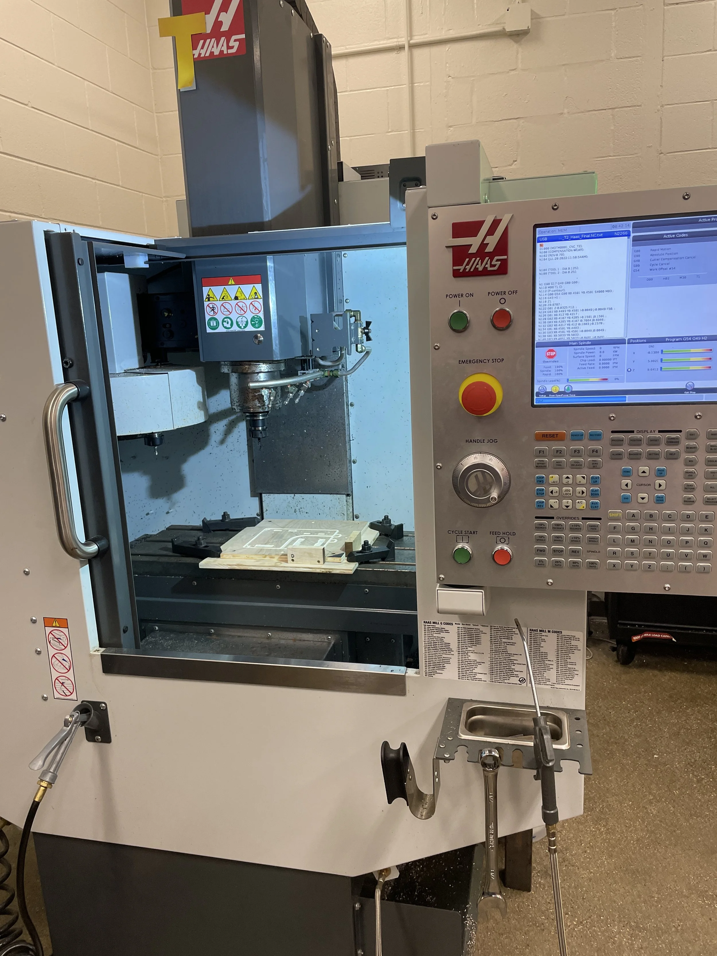
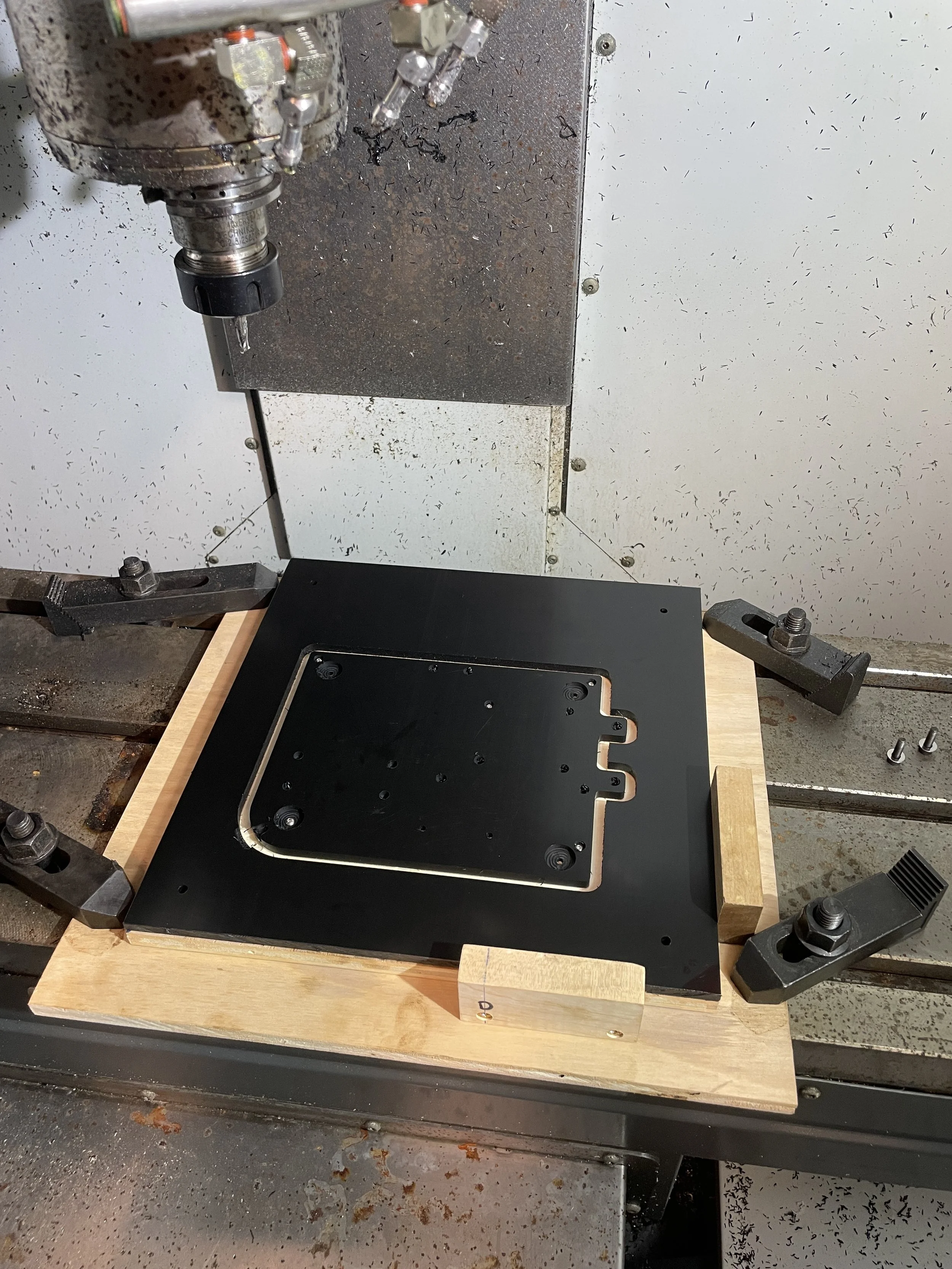
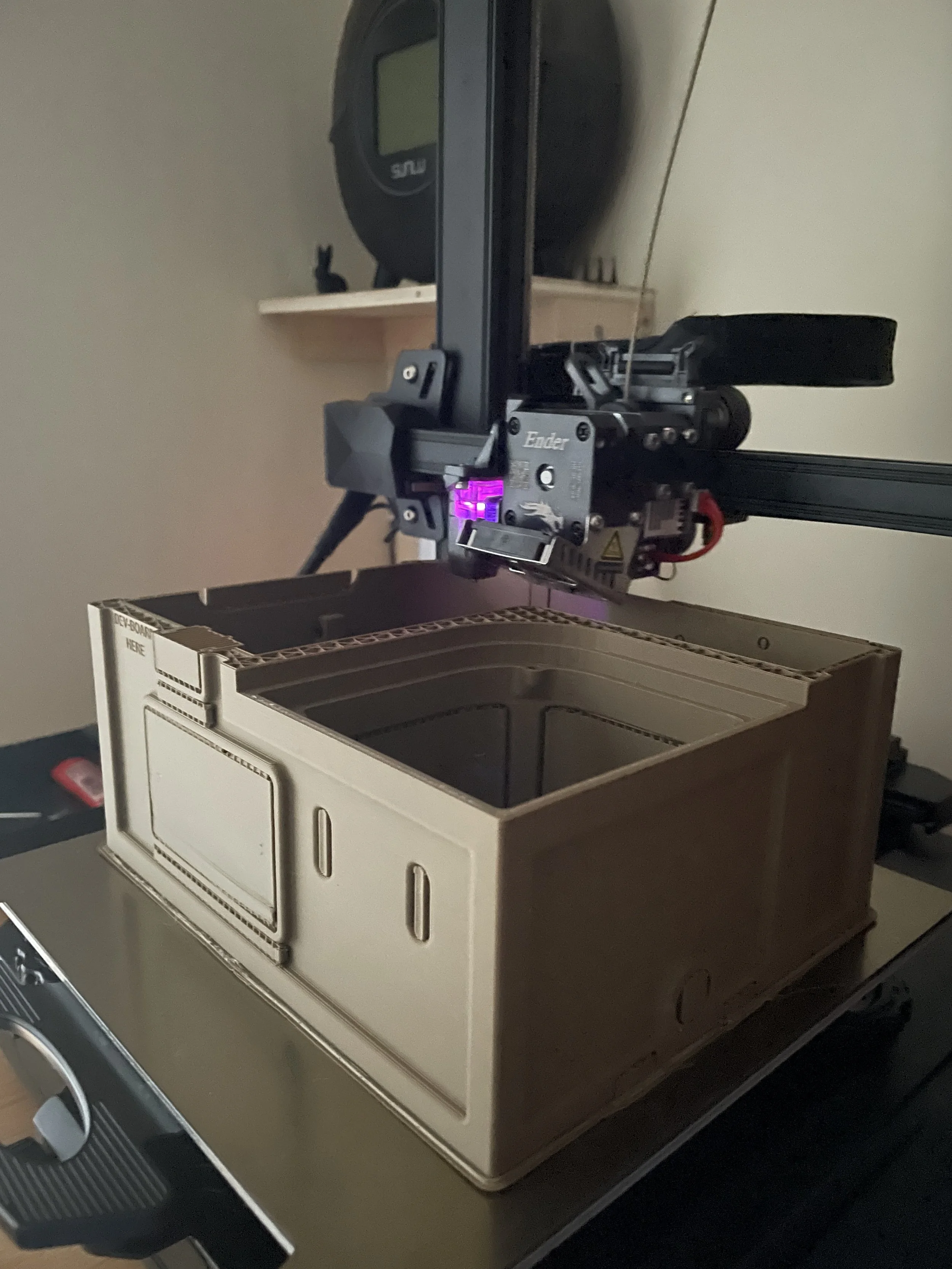
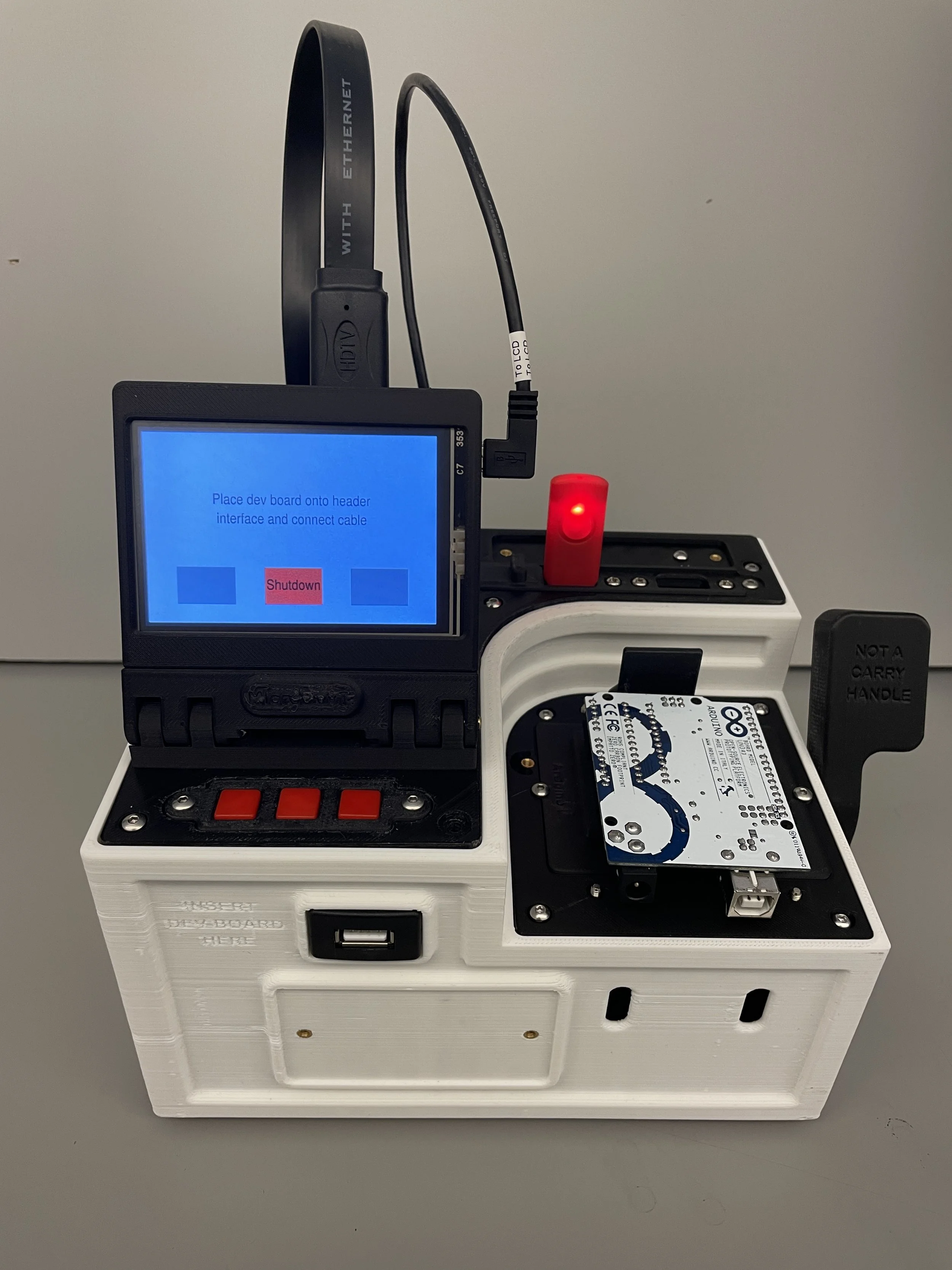
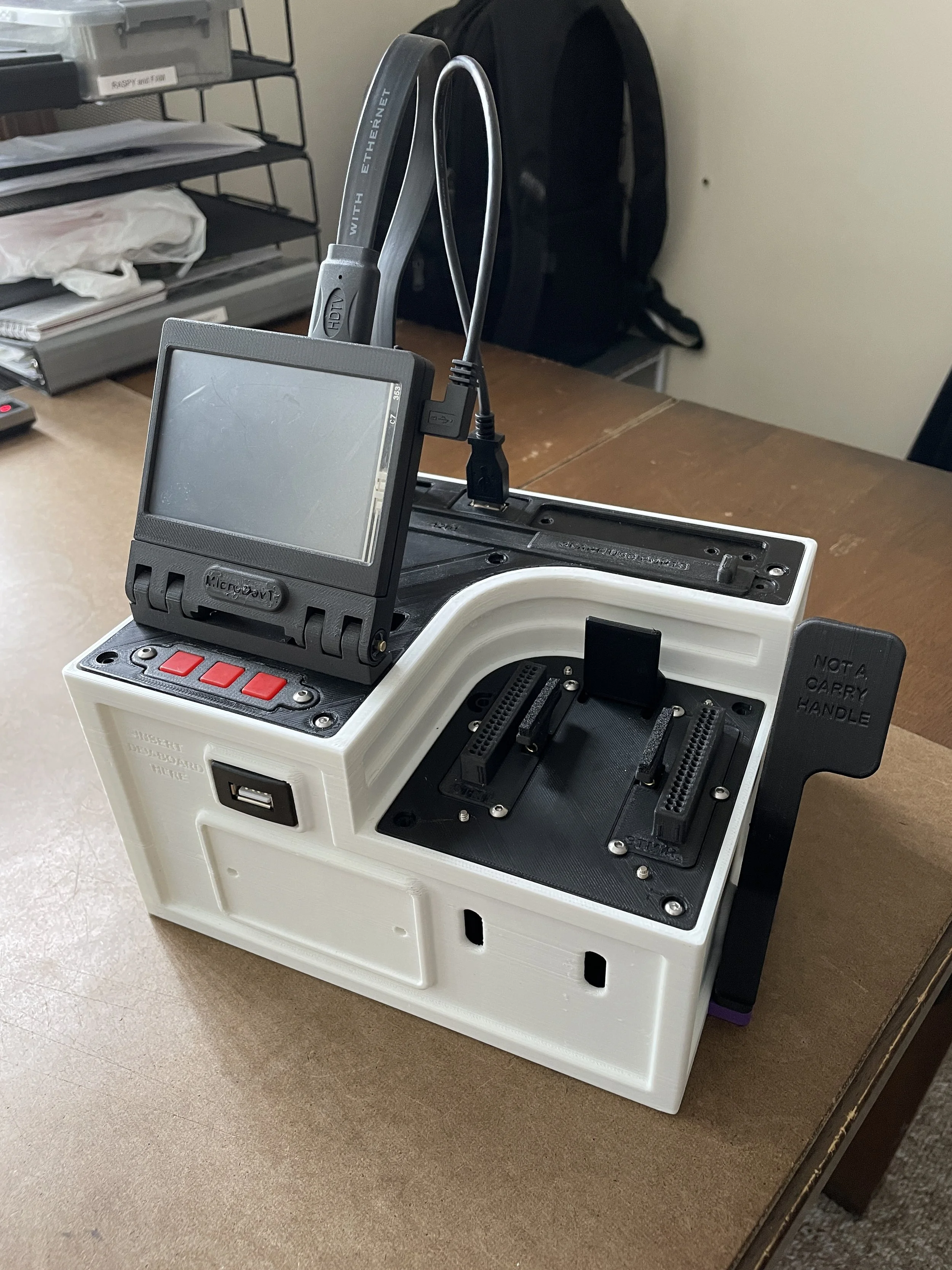
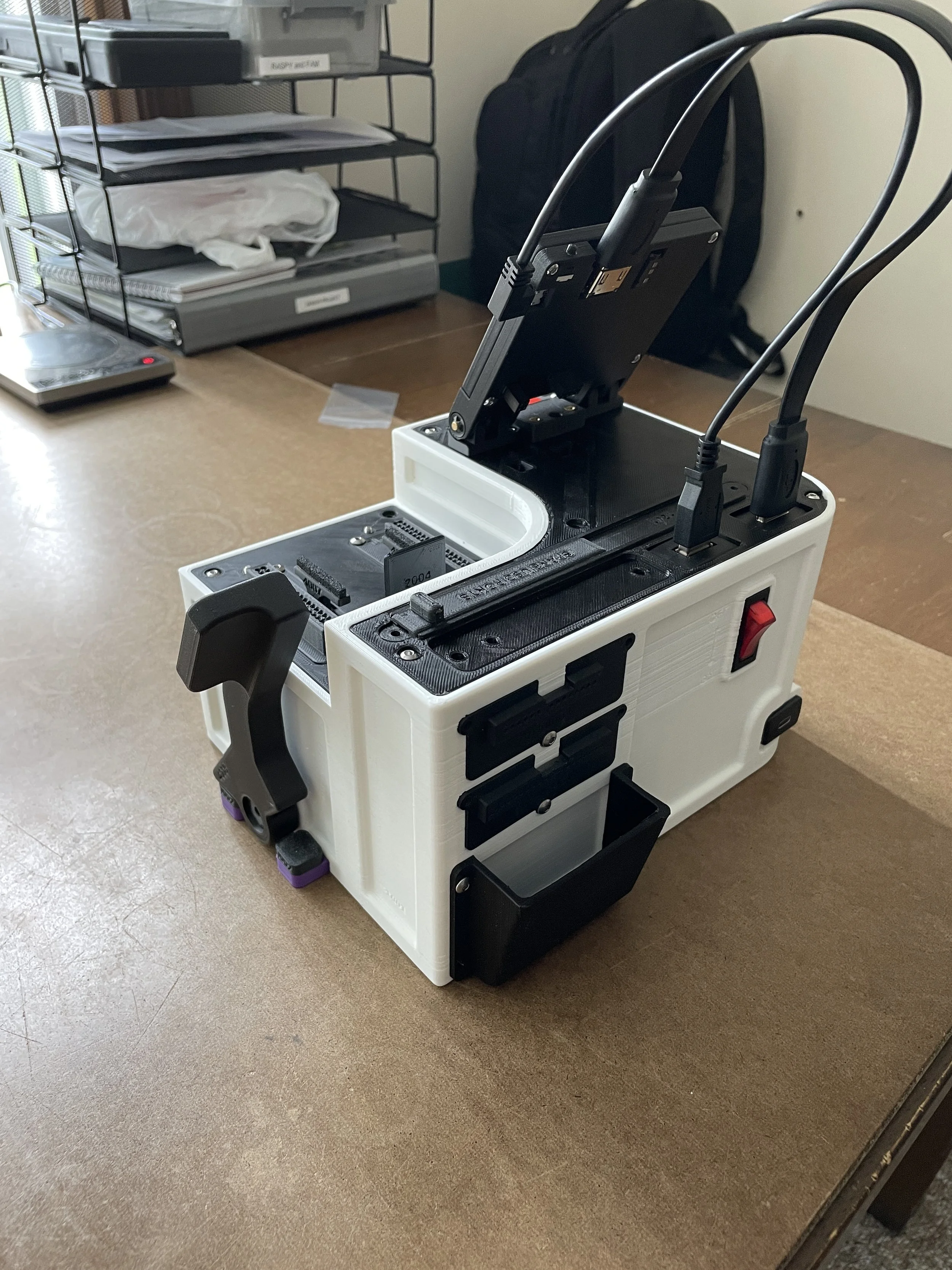
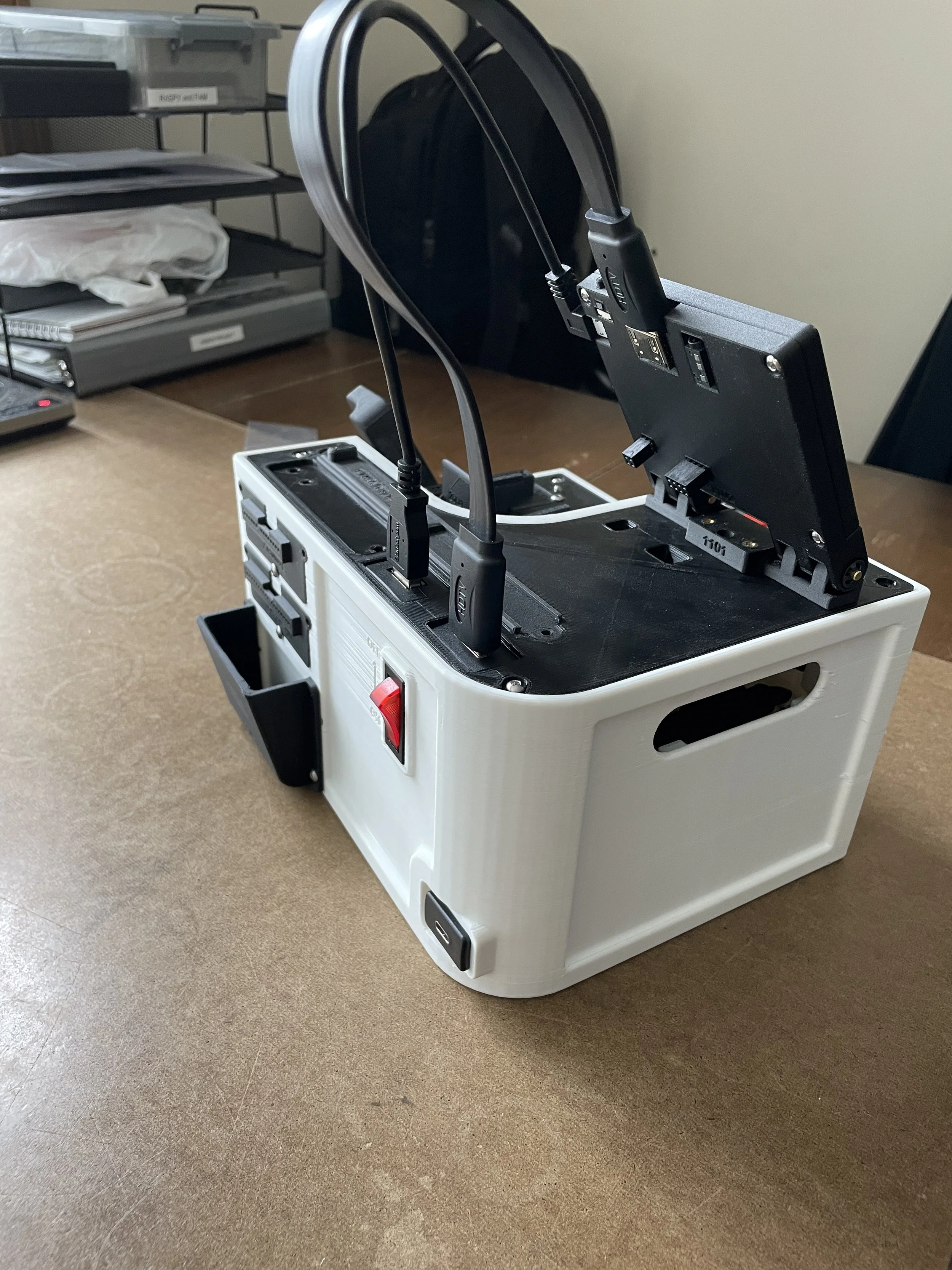
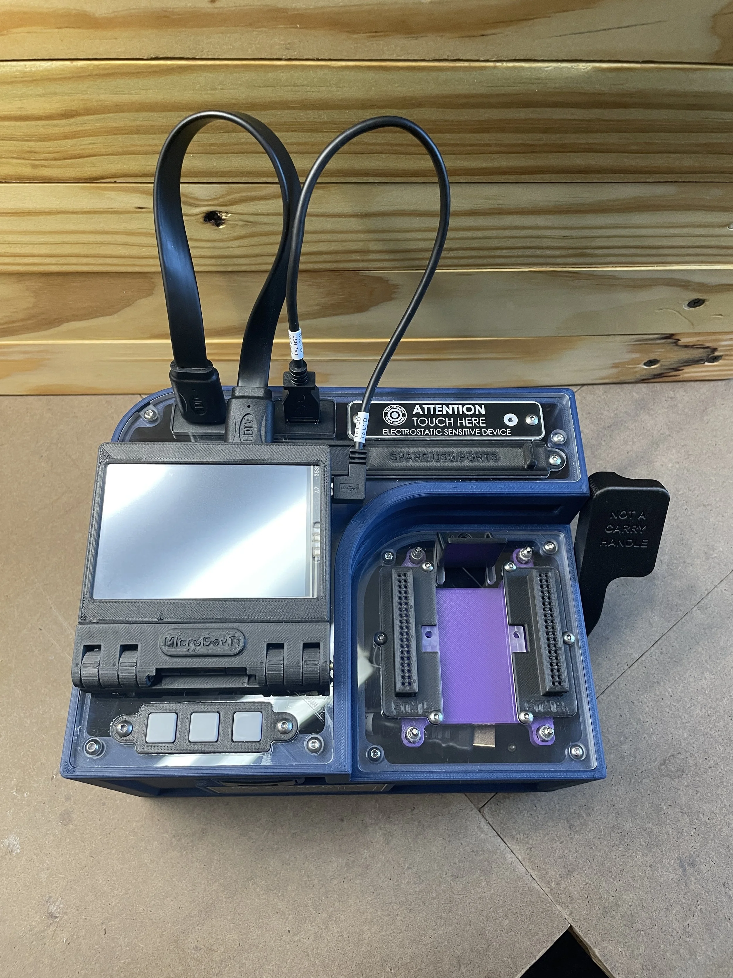
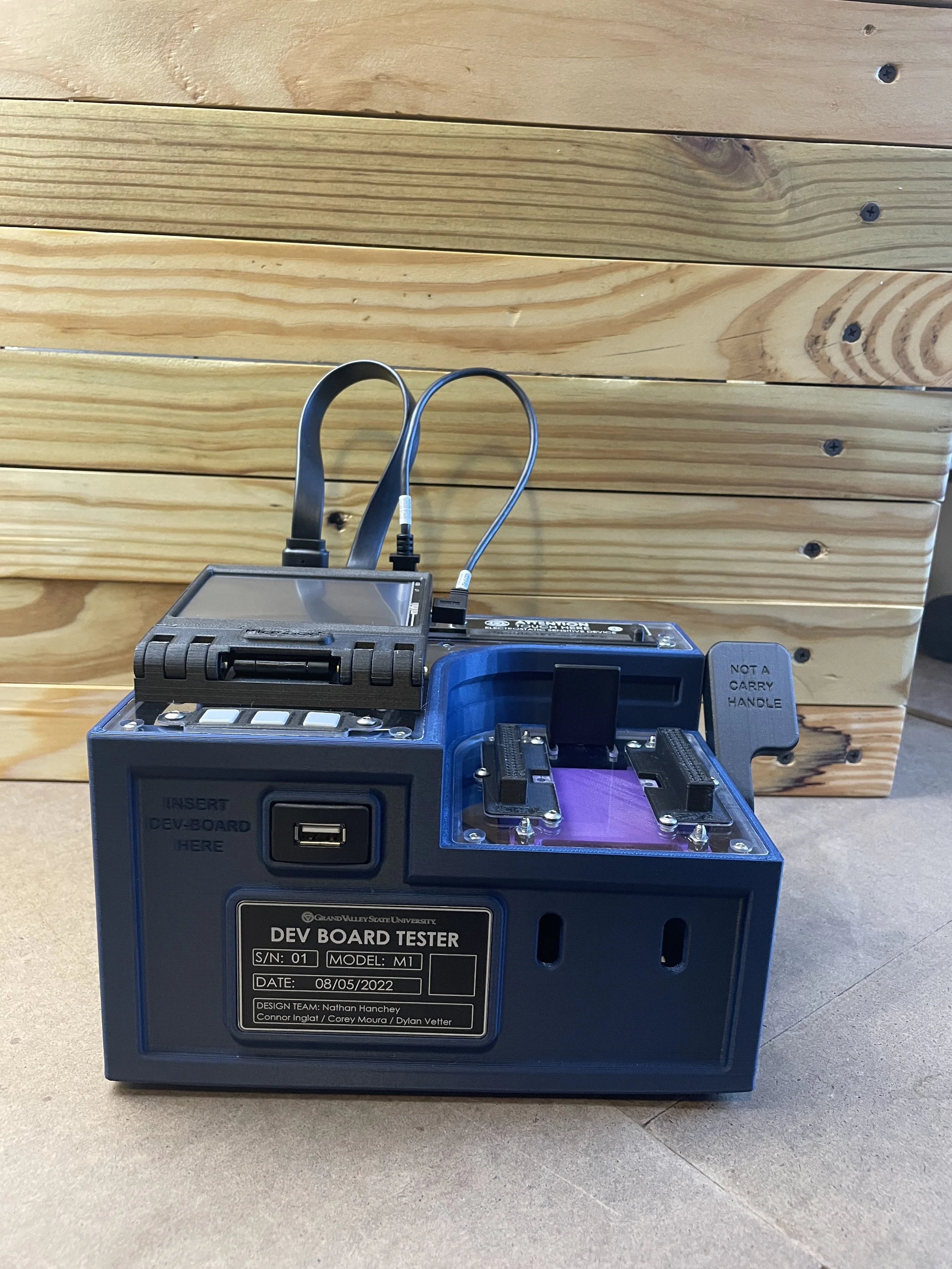
Mechanical Design
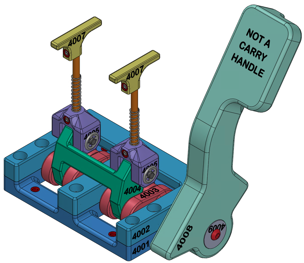
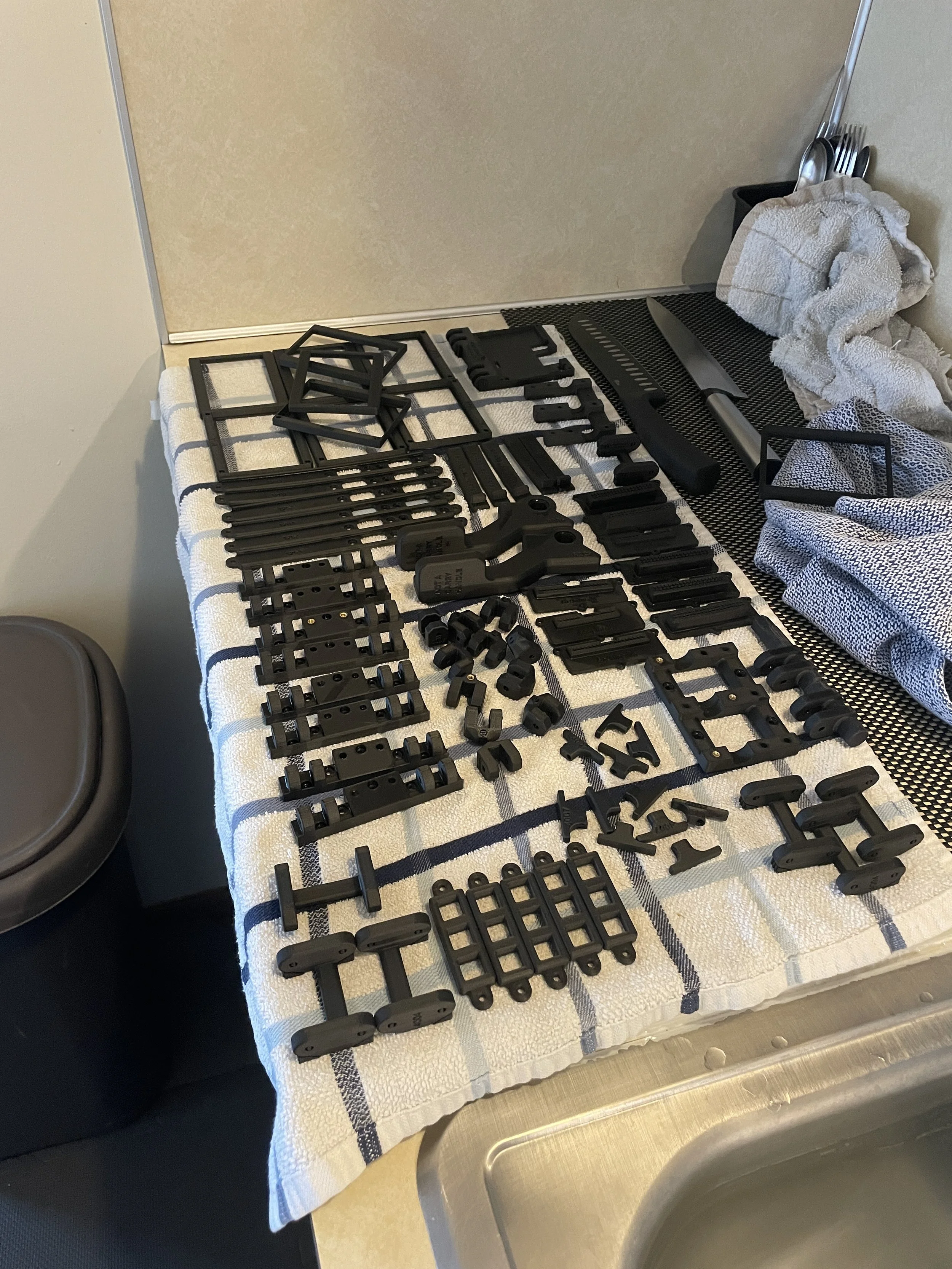
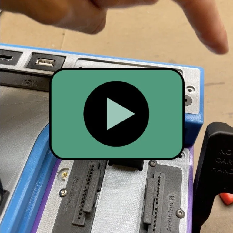
The devices were 3D printed in PLA and carbon fiber nylon and include a CNC milled polycarbonate top and ABS bottom. An ejection mechanism allows safe removal of the subject board from the device’s pin interface. The design of this interface allows it be quickly reconfigured to accept the Arduino Uno or STM32 microcontrollers.


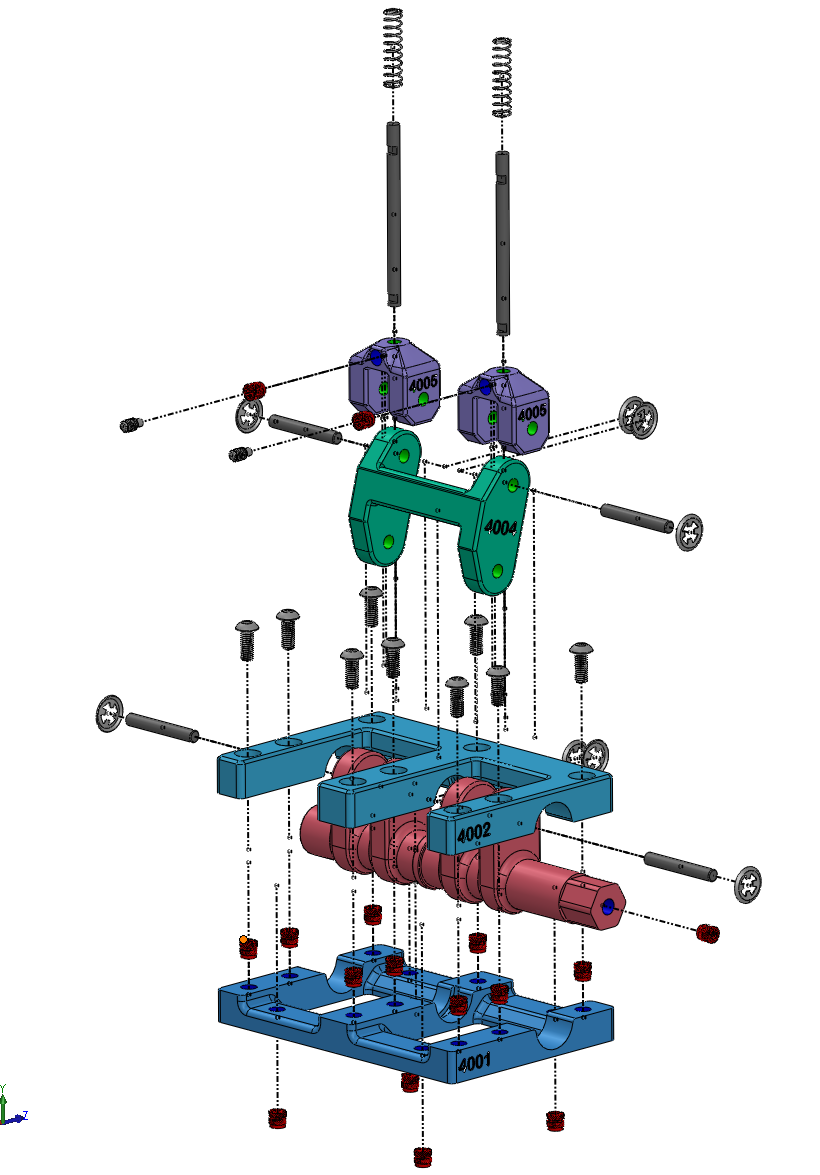


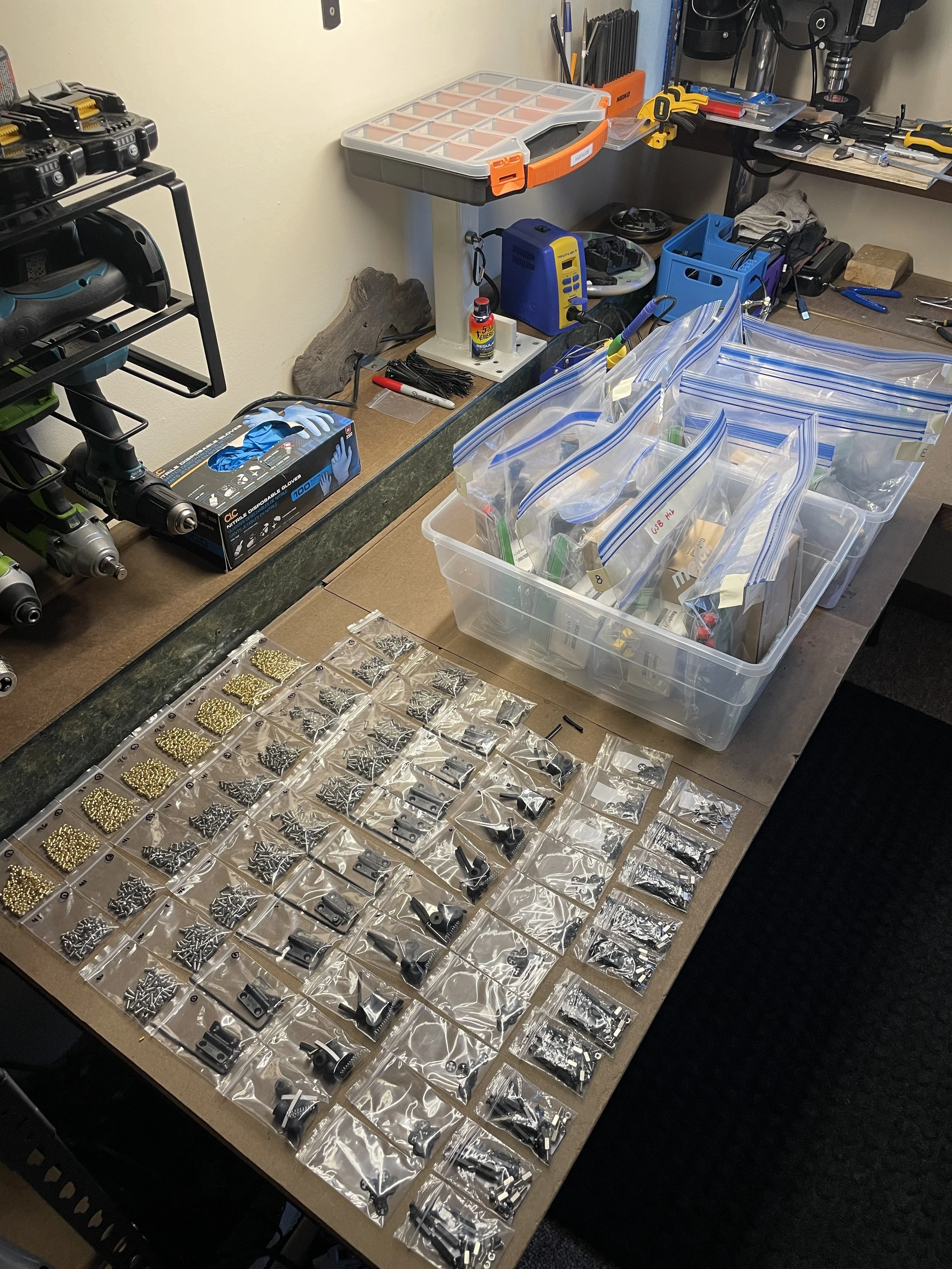
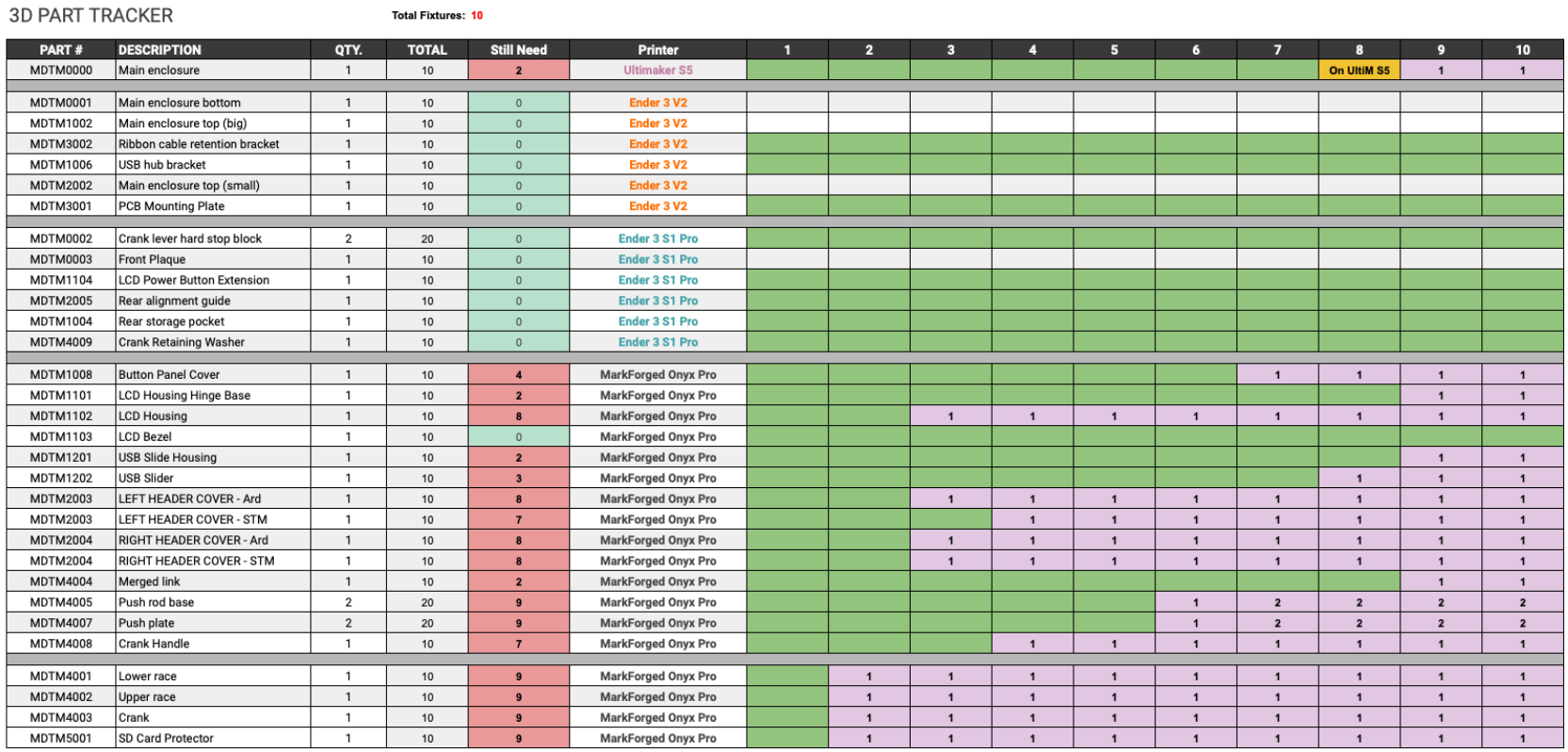
Production Run
Each device is composed of ~60 parts plus fasteners and heat set inserts. A part tracking excel document was generated to maintain accountability and organization during this phase.

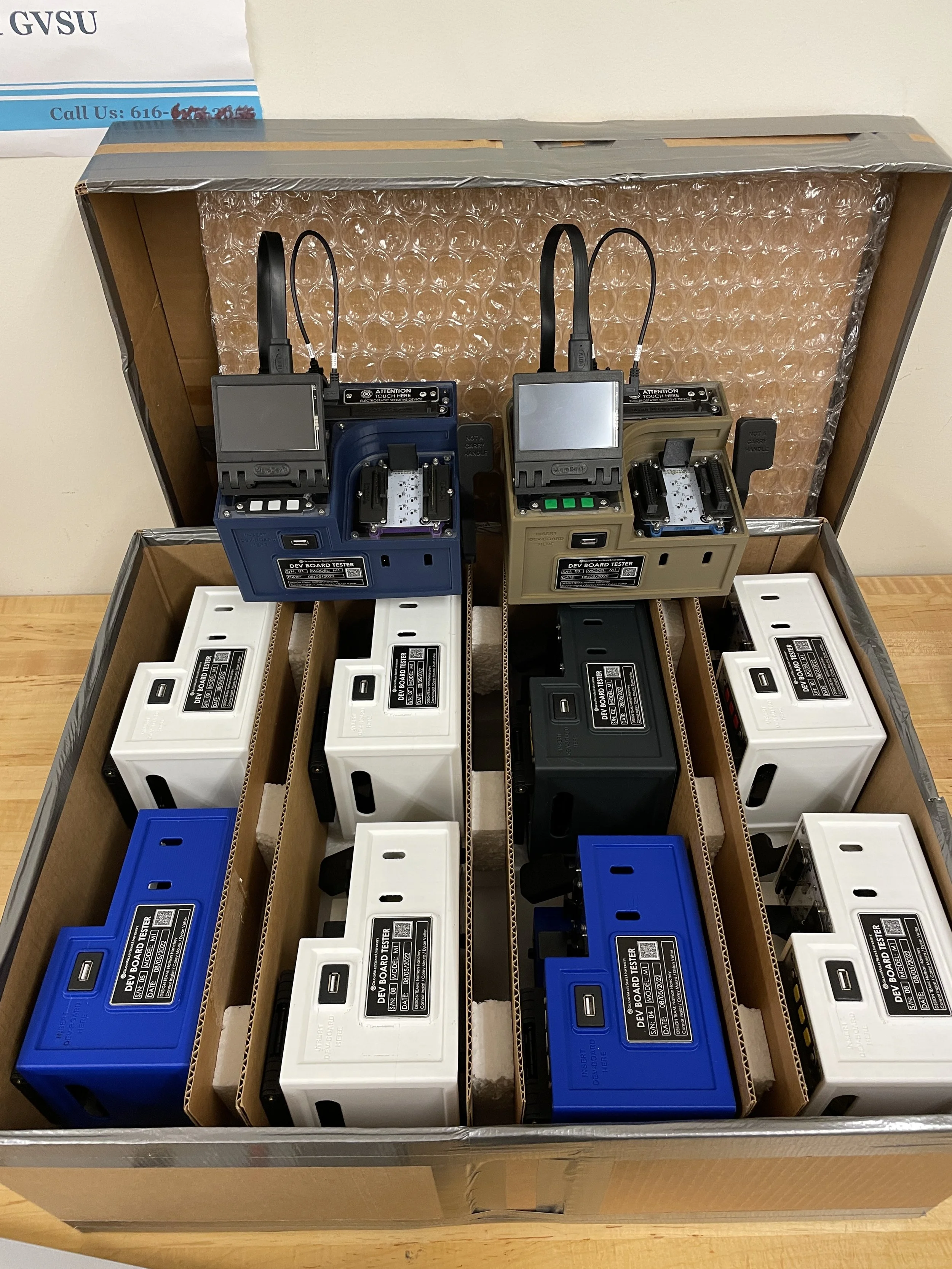


End Result
Due to the supply chain shortage of Raspberry Pies, only 3/10 devices were fully functional. Each of the 3 devices were quality tested and verified to function properly.

Videos
Short Demo
Laser Engraving
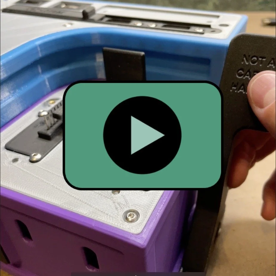
Ejection Assembly
USB-C Cover
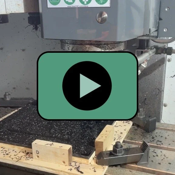
Machining ABS
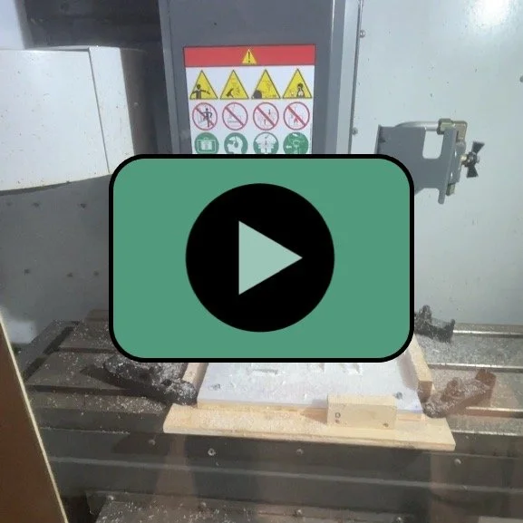
Machining Polycarbonate
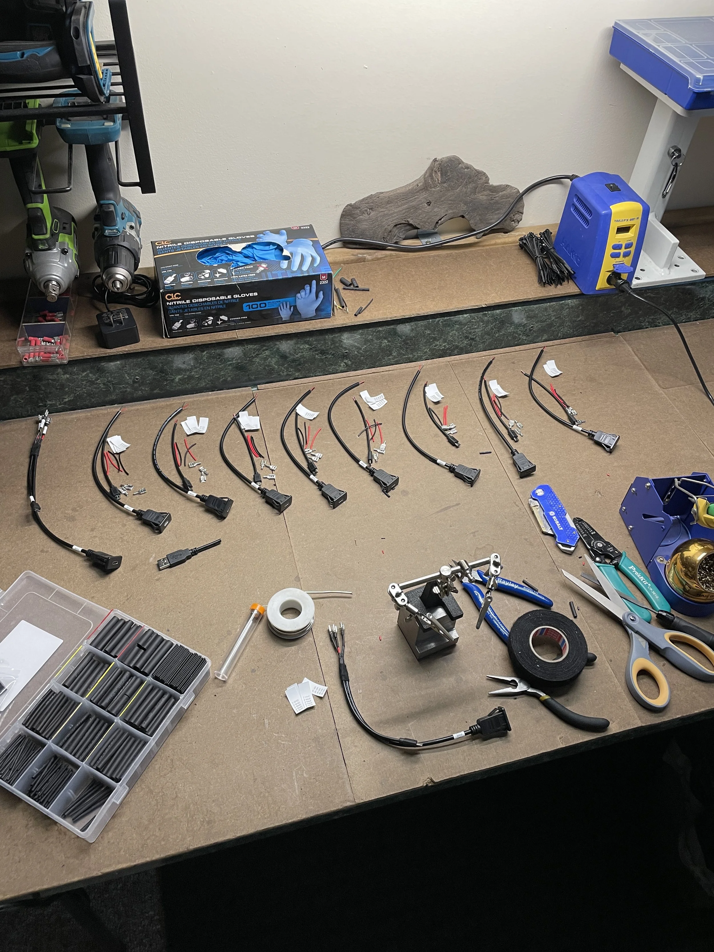
Wiring Harnesses
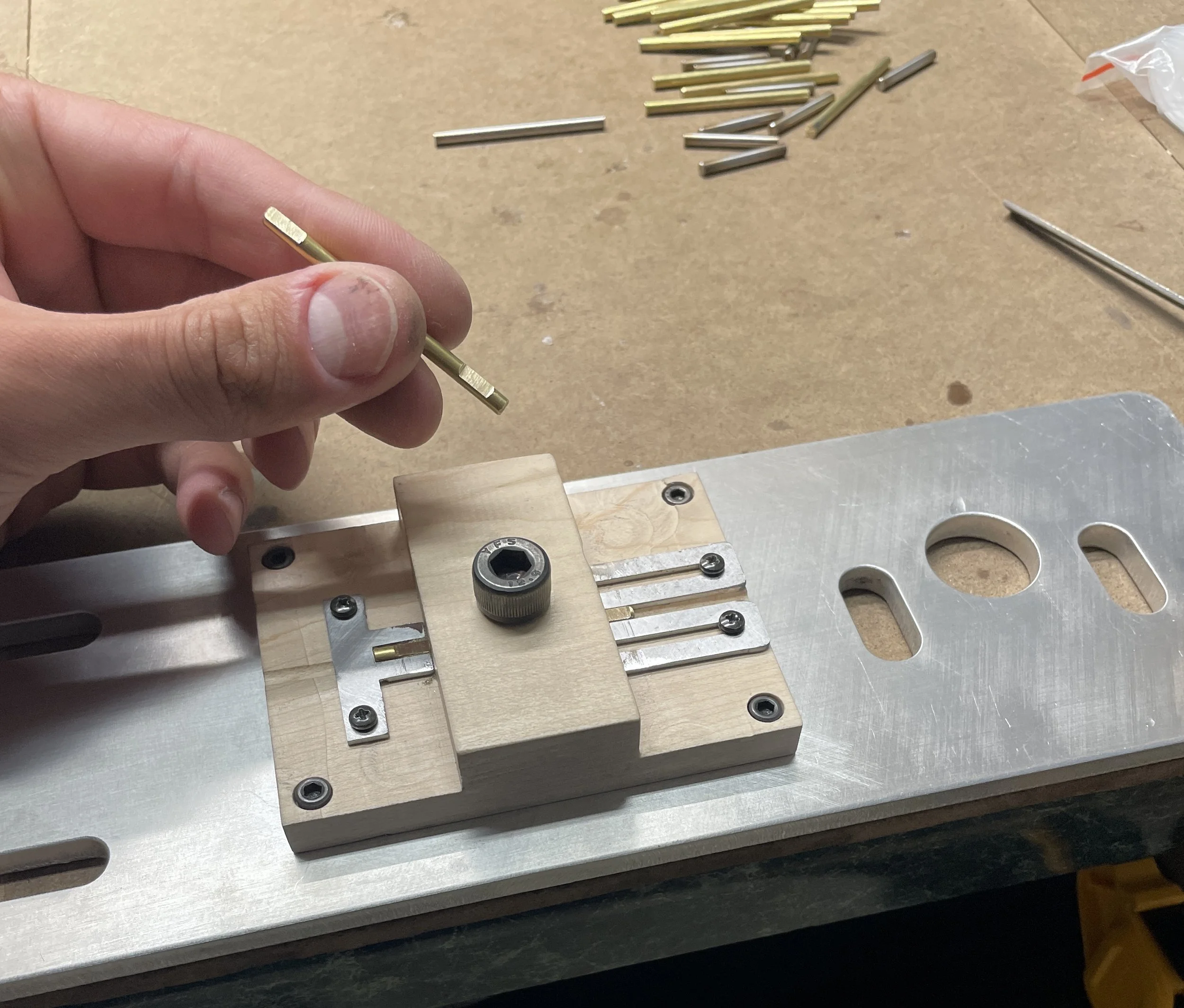
Parallel Flats